High-powermicrowave (HPM) have important applications in the field of electroniccountermeasures、radars、particle accelerators, and etc.There are several kinds of microwave devices for high power microwave (HPM)generators, such as relativistic klystron amplifier(RKA)[1, 2, 3],magnetron, backward wave oscillator (BWO)[4], traveling wave tube(TWT)[5], gyrotron, vircator[6], and transit tubeoscillator[7]. Some of them are oscillators, and others areamplifiers. Amplifiers become increasingly important in HPM development becausethe power limitation become obvious for a single device in recent years, andthe power adder with amplifiers is a better way to exceed this limitation. Therelativistic klystron amplifier (RKA) is a typical device among HPM amplifiers[1, 8].Currently, the simple three-cavity klystron structure has been widely usedbecause the oscillation of nonworking modes can be easily avoided in thisstructure[9]. But the gain of the three-cavity klystron is lower (30dB), so it means that the seeding rf power of MW level is required to obtainthe output power at the level of GW.
And in aklystron amplifier, the idler cavity can efficiently increase the gain of thedevice,but it alsocause oscillation of nonworking modes. Therefore, the non-working modes’suppression in the four-cavity relativistic klystron amplifiers becomes veryimportant[10, 11]. Compared with the three-cavity relativisticklystron, the four-cavity relativistic klystron has advantages at the gain.With the gain of 60 dB, the seeding rf power of kW level can produce the outputpower at the level of GW, so it will greatly reduce the device’s size and cost.However, the nonworking modes’ oscillation will be easily excited in suchstructure, and the normal operation of the device is severely affected. Tosuppress nonworking modes’ oscillation in the four-cavity relativistic klystronamplifier, this paper applies PIC simulation software to study the performanceof the tube and optimize the structure.
1 Cold Cavity’s ParametersThe structure of a relativistic klystronamplifier composes of the input cavity, the idle cavity, the drift tube, theoutput cavity, and the rf absorber for non-working modes’ suppression. In thispaper, in order to achieve the gain of more than 60 dB,two idle cavities (shown in Fig. 1) is used in the structure. The resonant frequency of each cavity is shown inTable 1. In Table 1, two idle cavities’ resonant frequencies are different,there are two reasons: 1) the gap voltage in the second idle cavity will betuned to the required value due to such difference, 2) the structure’sfrequency band can be broadened. And the resonant frequency of the outputcavity is kept to be the same with the operating frequency. Meanwhile, the Qvalue of the output cavity should be moderate. The field strength in the cavitygap will be too small for the output cavity to exchange energy with thebunching electronic beam effectively if the Q value is too low. On theother hand, the field of gap will be too high and make too many electrons’returning if the Q value is too high. In this paper, Q value ofthe output cavity is 11.15.
| Table 1 Frequency and Q value of thecavities |
 |
| Fig. 1 Structure of a four-cavityrelativistic klystron amplifier |
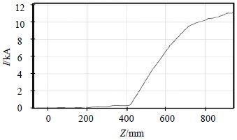
Fig. 1 showsthe geometry structure used for simulations. The injection microwave power is 2kW at the frequency of 2.88 GHz. Electron beam’s parameters are current 15 kAand voltage 1.2 MV. And the guide magnet field is 1T. Changes of thefundamental harmonic modulated current amplitude vs axis Z are shown inFig. 2. After the electron beam passes through input cavity gap, we achieved afundamental modulated current of 51 A and modulation depth is 3.4% at 138 mmaway from the input cavity as shown in Fig. 2. After optimizing the distancebetween the input cavity and the first idle cavity, we achieved a fundamentalmodulated current of 325 A and modulation depth is 21% at 258 mm away from thefirst idle cavity. After optimizing the distance of two idle cavities, themodulation depth can reach 75% at the output cavity (as shown in Fig. 2).
 |
| Fig. 2 Fundamentalmodulated current vs axis Z |
In order to suppress the nonworkingmodes’ oscillation, we have studied the relation between the output cavity gapvoltage and the beam modulation depth ${i_1} = {I_1}/I$. According to theequivalent circuit of the output cavity [4], the output cavity gapvoltage is given by:
| $V=M{I_1}R$ | (1) |
Here I1 is thefundamental current of electron beam, R is shunt impedance of outputcavity, and M is the coupling coefficient. And the cavity shuntimpedance R directly reflects efficiency of the interaction betweencavity field and electron, and is given by[5]:
| $R = \frac{{{V^2}}}{{2{\rm{(}}{P_S}{\rm{ + }}P{\rm{)}}}}$ | (2) |
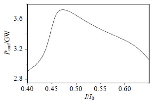
Here ${P_S}$representsthe internal power loss of the resonator, and P the output power of theoutput cavity. Effects of beam modulated depth and gap impedance on the outputpower are shown Fig. 3 and Fig. 4. In Fig. 3 and Fig. 4, the output power reachesthe maximum value when R and ${i_1} = {I_1}/I$ is optimized. That’s mainly because the gap voltage may be too large (according toEqu. (1) and Equ. (2)) when the gap impedance R or beam modulation depth ${i_1} = {I_1}/I$ is too large.
 |
| Fig. 3 Effects of beam modulation to the outputpower |
 |
| Fig. 4 Effects of gap impedance to the outputpower |
Effects of changes about the distance between the beam and the drifttube wall to the output microwave are listed in Table 2. It is shown thatelectron reflection can be effectively suppressed by increasing distance D between the beamand drift tube wall. The phenomena can be explained by the coupling coefficientM decreasing and the beam-microwave interaction reducing. In order tosuppress the electron returning and increase the output microwave power, thedistance between the beam and the drift tube wall before second cavity ischose to be 2 mm as shown in Fig. 1. According to the effect of the aboveparameters' (R、${i_1}$ and D) on the output microwave power, we have alsooptimized the structure by PIC simulation codes. We obtained a stable outputmicrowave with the power reaches 3.05 GW,efficiency of 22%, and gain of 63 dB when the seeding rf power is 1.5 kW.
| Table 2 Effects of changes aboutdistance between the beam and drift tube wall to the output microwave |
The experiment is performed on the LinearTransformer Driver (LTD) accelerator, which can operate in the single pulseregime at a maximum voltage of 950 kV with pulse duration of 150 ns. Theseeding rf power for the high gain RKA is an S-band klystron with a peak powerof 5 kW and frequency of 2.86 GHz. Under conditions of the beam voltage of 900kV, and the current of 8 kA, we have investigated the influence of the input RFpower on the output power. The output power will be saturated when the input RFpower is more than 1.5 kW, the maximum output power reaches 3.05 GW with theinput power of 3 kW, and the corresponding gain is 60 dB. With the input rfpower of 1.38 kW, the maximum radiation power reaches 1.9 GW and the gain is61.4 dB.
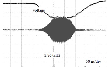
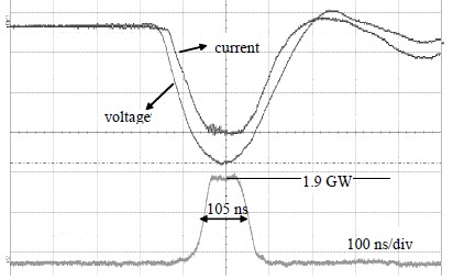
Fig. 5 is the waveform and spectrum of theoutput microwave with the input power of 1.38 kW in the experiment. It can beobserved that there is no other frequency in the spectrum as shown in Fig. 5.Typical waveforms of the diode voltage, diode current, and the output microwavesignal measured in the radiation field are shown presented in Fig. 6. The gainof 61.4 dB (the seeding rf power 1.38 kW) is achieved in the experiment, andits pulse duration is more than 100 ns.
 |
|
Fig. 5 Waveform and spectrum of the output with input power of 1.38 kW |
 |
|
Fig. 6 Waveformsof the diode voltage, diode current, and microwave detector signal |
By using the 2.5-dimensional particle simulation software, we havedesigned a four-cavity relativistic klystron for a high gain amplifier and haveanalyzed the high-frequency performance of the klystron. With the seeding microwave of 2.86 GHz frequencyand
1.5 kW inputpower, we have obtained output microwave with power of 3.05 GW, efficiency of22%, and gain of 63 dB. The corresponding experiment is carried out on the LTDaccelerator. With the seeding microwave of 2.86 GHz frequency and 1.38kWseeding rf power, the gain of 61.4 dB and the output power of GW level areexperimentally achieved without the nonworking mode excitation.
| [1] | BENFORD J, SWEGLE J A, SCHAMILOGLU E. High power microwaves[M]. London: CRC Press, Taylor and Francis Group, 2007. |
| [2] | KLIMOV A I, KURKAN I K, POLEVIN S D, et al. A multigigawatt X-band relativistic backward wave oscillator with a modulating resonant reflector[J]. Technical Physics Letters, 2008, 34(3): 235-237. |
| [3] | XIAO R, CHEN C, DENG Y, et al. An X-band overmoded relativistic klystron[J]. Physics of Plasmas, 2014, 21(11): 1131011-1131016. |
| [4] | LI Zheng-hong, ZHOU Zhi-gang, QIU Rong. Beam-loaded frequency shift study in an over-sized backward wave[J]. Physics of Plasma, 2014, 21(10): 1031051-1031056. |
| [5] | LI Zheng-hong, ZHOU Zhi-gang, QIU Rong. Influence of beam-loaded effects on phase-locking in the high power microwave (HPM) oscillator[J]. Physics of Plasma, 2014, 21(6): 0631011-0631016. |
| [6] | CLEMENTS K R, CURRY R D, DRUCE R, et al. Design and operation of a dual vircator HPM source[J]. IEEE Transactions on Dielectrics and Electrical Insulation, 2013, 20(4): 1085-1092. |
| [7] | LING J, ZHANG J, HE J, et al. A novel coaxial Ku-band transit radiation oscillator without external guiding magnetic field[J]. Physics of Plasmas, 2014, 21(2): 023114(1-7). |
| [8] | WILSEN C B, LUGINSLAND J W, LAU Y Y, et al. A simulation study of beam loading on a cavity[J]. IEEE Transactions on Plasma Science, 2002, 30(3): 1160-1168. |
| [9] | ZAITSEV N I, GVOZDEV A K, ZAPEVALOV S A, et al. Experimental study of a multimegawatt pulsed gyroklystron[J]. Journal of Communications Technology and Electronics, 2014, 59(2): 164-168. |
| [10] | BATISCHEV D V, PAVLENKO A V. On designing electromagnetic drives operating under conditions of high vibrations[J]. Russian Electrical Engineering, 2012, 83(8): 423-431. |
| [11] | VINTIZENKO I I. Modifications of a relativistic magnetron[J]. Technical Physics, 2014, 59(1): 113-118. |
 2015, Vol. 44
