ISSN
ISSN 


-
随着电子通信技术的发展,宽带双圆极化阵列天线具有了很强的抗干扰能力和抗衰减能力,在卫星通信技术中得到了广泛应用[1-6]。天线性能的优劣直接决定了通讯系统性能的好坏,因而国内外学者对天线开展了一系列的研究。文献[7]采用双层圆形辐射贴片开不同的槽来实现双圆极化,经组阵后天线具有高辐射效率(高于65%)和低旁瓣(小于–20 dB)的特性。文献[8]研究了一种旋转布阵式的双频双圆极化2×2阵列,获得了隔离度大于26 dB以及带内轴比低于1.2 dB的特性。
文献[9]采用上下分层的正交耦合馈电实现双极化特性。两个极化端口阻抗带宽为52%,极化隔离度在39 dB以上。文献[10]介绍了一种低剖面宽带广角扫描圆极化阵列,结果表明在8~9.1 GHz范围内,其扫描下降3 dB以内的扫描角超过±60°。文献[11]采用4个按顺时针旋转的L形贴片构成宽带圆极化天线,10 dB阻抗带宽达到了92.8%,3 dB轴比带宽为67.5%,峰值增益为12.4 dBi。
本文采用双层圆形辐射贴片,利用环形电桥实现双圆极化馈电,贴片四周采用金属柱与环形金属带作为寄生单元,设计出一款工作在1.8~2.36 GHz的双圆极化宽带层叠微带天线。天线单元工作频带内的波束宽度优于110°,峰值增益5.9 dBi,交叉极化抑制度优于20 dB,前后比优于28 dB。采用5个单元组成了非规则面阵,阵列合成增益实测大于11.5 dBi,±55°扫描增益高于9 dBi。
-
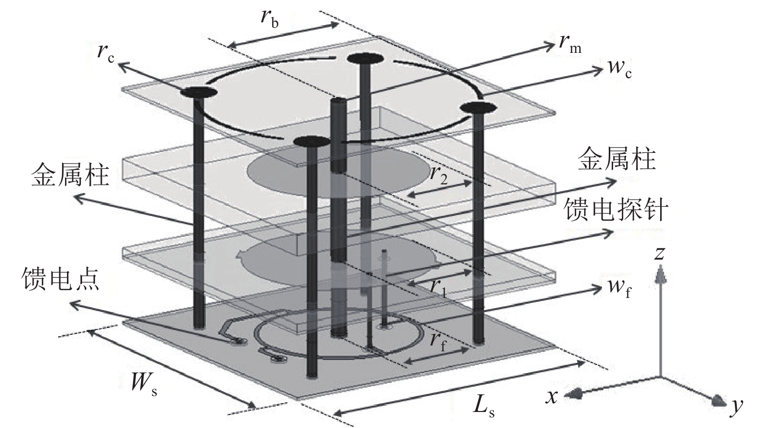
图1所示为天线单元,其尺寸为58 mm×58 mm×8 mm。天线一共有4层介质基板,最下层为介电常数2.2,厚度1 mm的带状线结构馈电网络层。其余为介电常数4.3的辐射贴片层,厚度由上往下分别为0.5、4.5、2 mm。
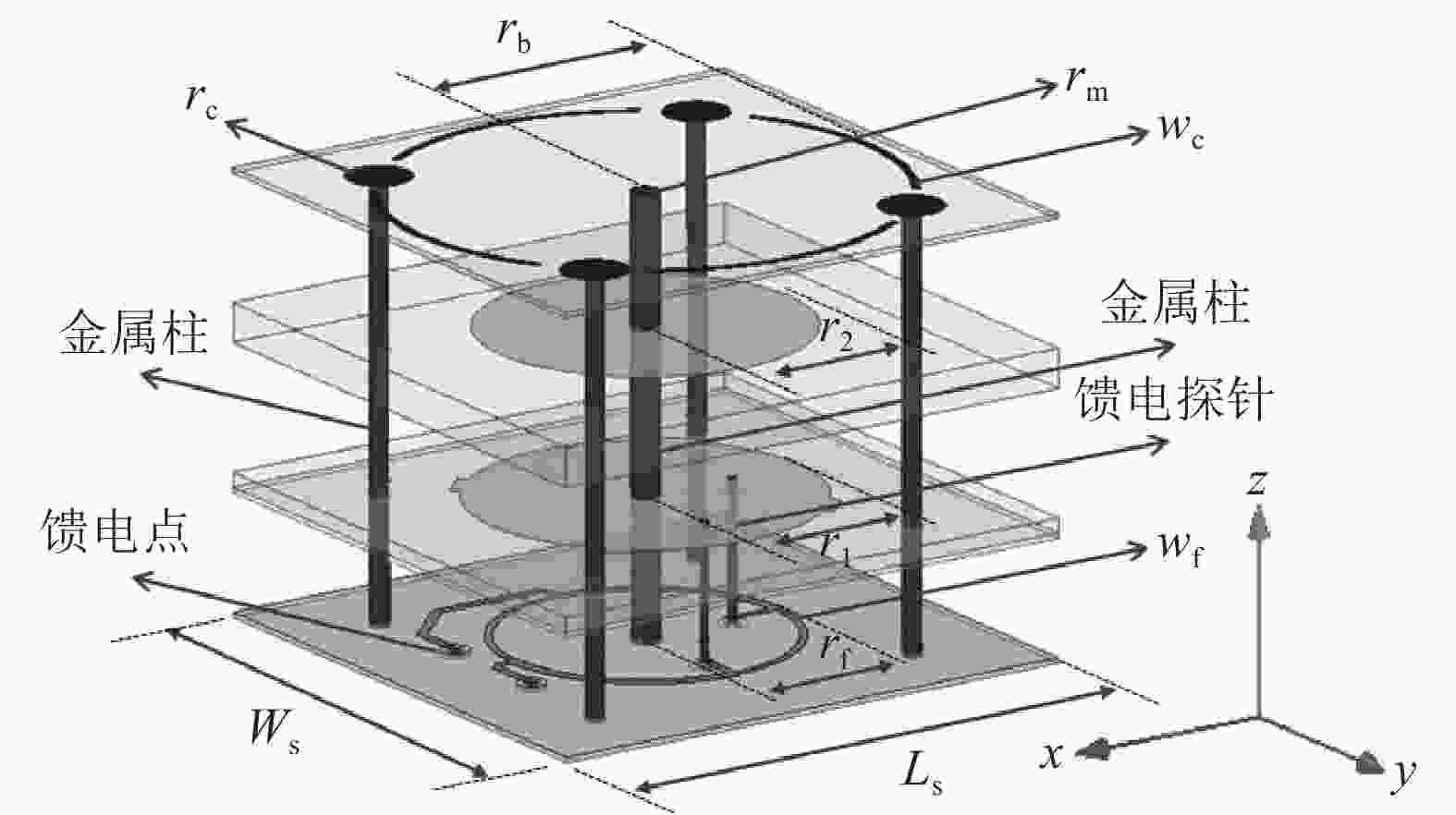
图 1 天线结构及尺寸参数图
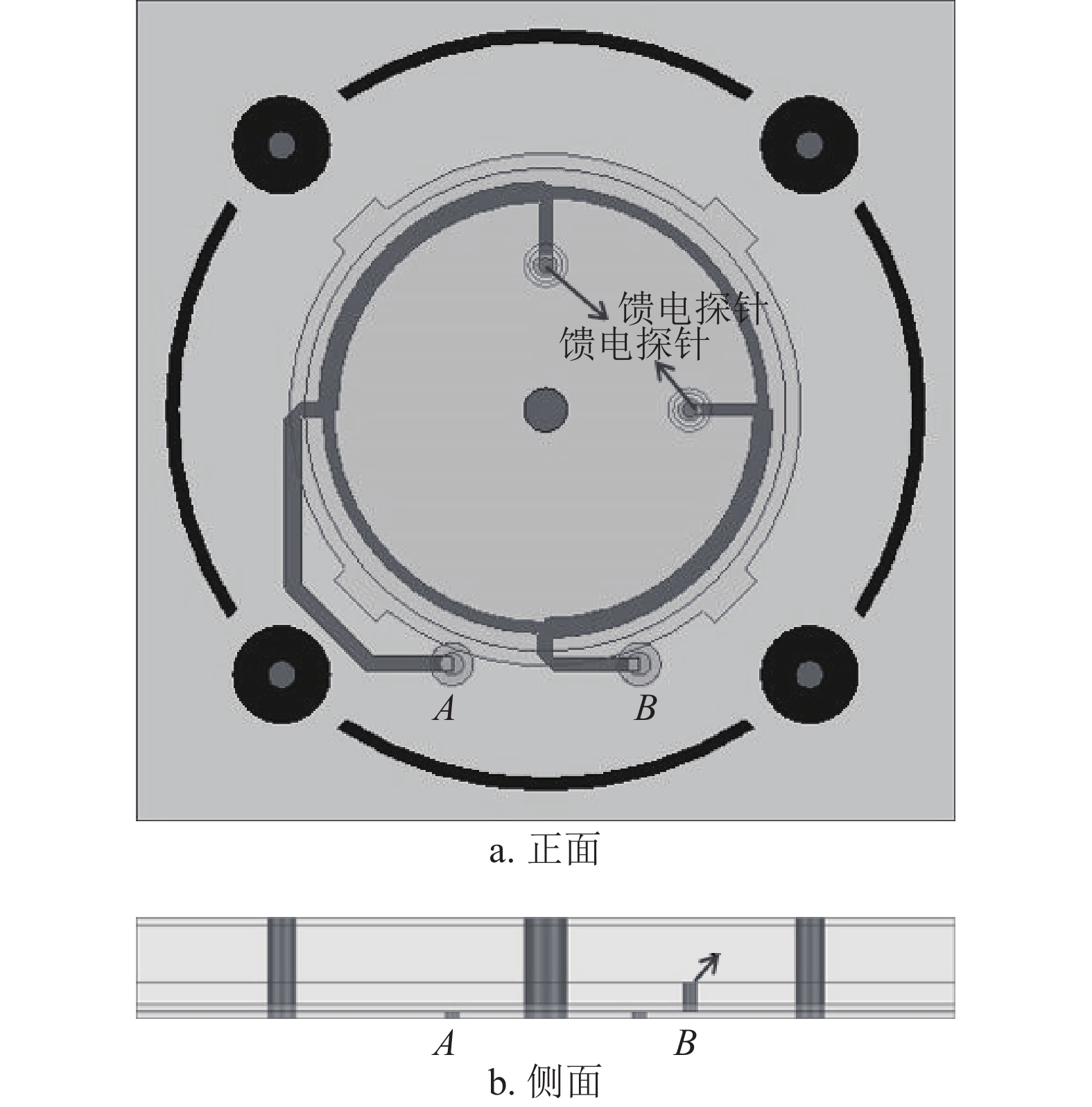
天线尺寸的具体数值见表1,而两个馈电探针的直径为1 mm,它们在电桥上相距四分之一波长,天线的两个馈电点分别对应圆极化的两个旋向。
表 1 天线的详细尺寸
mm 参数 取值 参数 取值 WS 58 LS 58 r1 16.6 rc 3.6 r2 15.6 rm 1.5 rf 10.5 wc 0.83 rb 25.9 wf 0.87 -
天线图如图2所示,馈电点A、B分别表示左旋和右旋圆极化端口。位于天线正中心的短路金属柱可抑制一些干扰模式,而辐射贴片周围的金属柱相当于顶部加载电容的单极子天线,它与天线顶层的环形金属带共同作用,起到了一定的展宽波束的效果。天线有两层辐射贴片,馈电信号通过两个相距四分之一波长的探针对下层辐射贴片进行馈电,位于上层的辐射贴片通过电磁耦合作用获得激励。
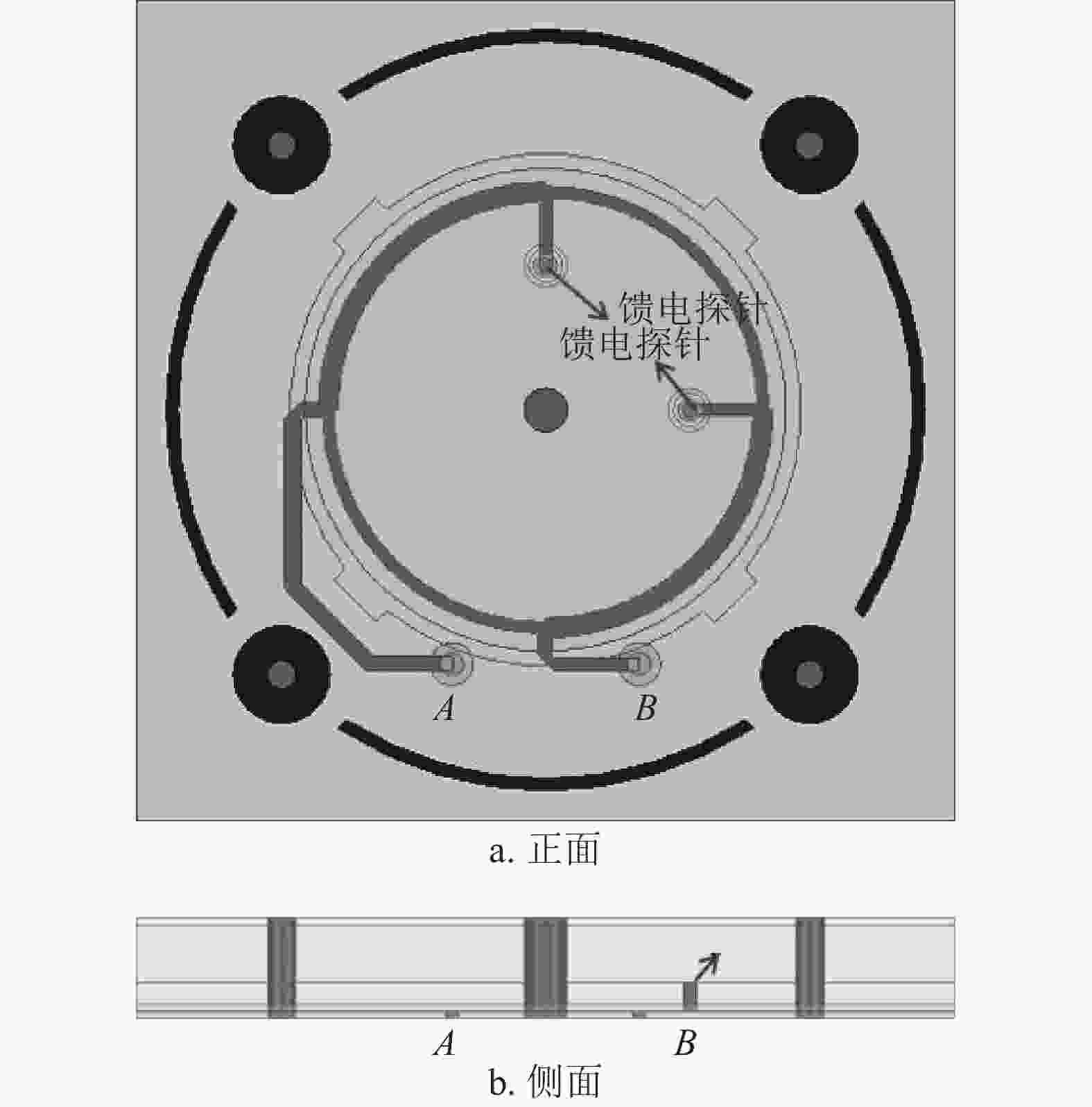
图 2 天线的正面图与侧面图
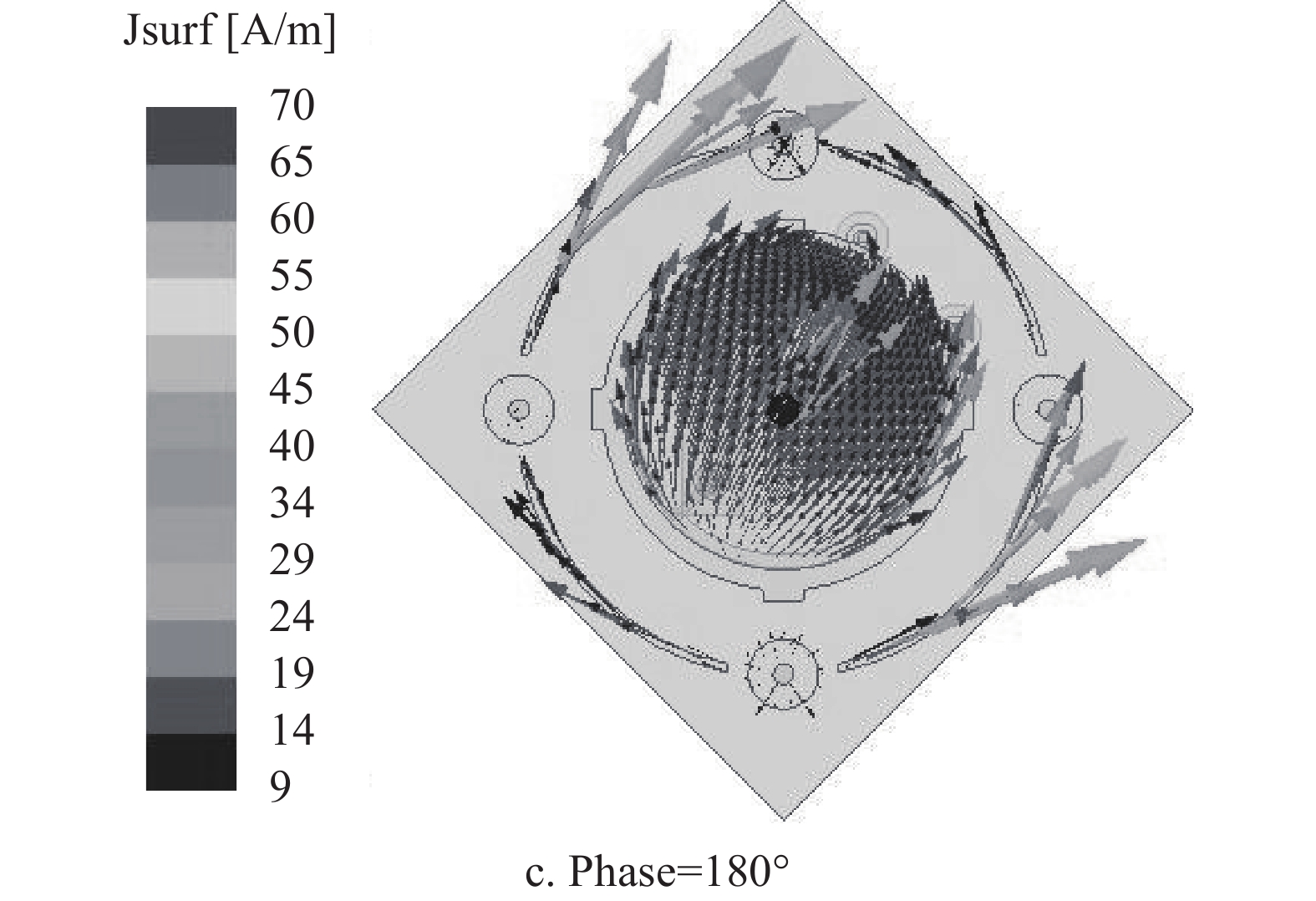
为进一步探究天线特性,采用全波仿真软件进行仿真分析。图3为右旋端口馈电时的电流分布(2.3 GHz),纵观天线在不同相位时的电流分布,其较好地实现了圆极化特性,其中环形金属带上有较强的电流,说明环形金属带参与了天线辐射。
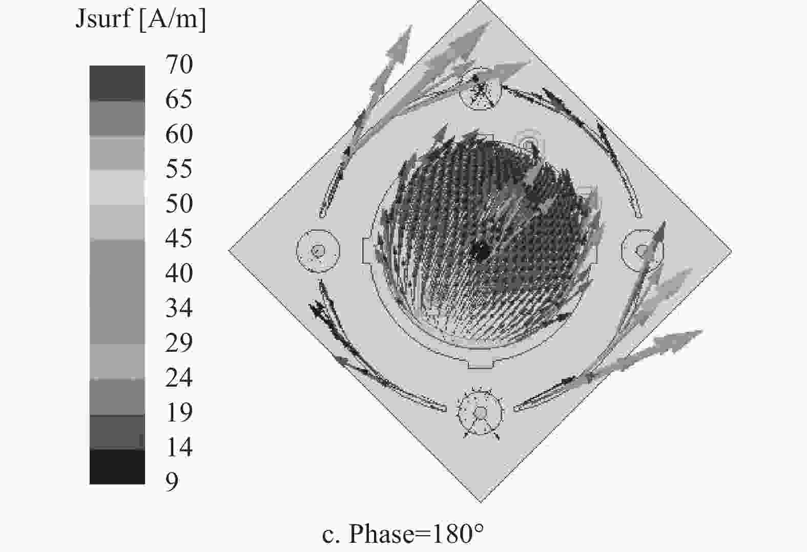
图 3 天线的电流分布图(右旋2.3 GHz)
-
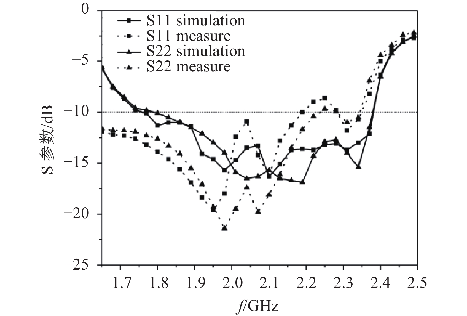
图4、图5分别为天线的S参数和轴比图。可以看出,天线的10 dB阻抗带宽为26.9%(1.8~2.36 GHz),实测结果略偏低频,3 dB法向轴比带宽为19.3%(1.92~2.33 GHz),实测结果与仿真结果一致性较高。两个端口(极化)的S参数结果比较接近,天线阻抗带宽要优于轴比带宽。
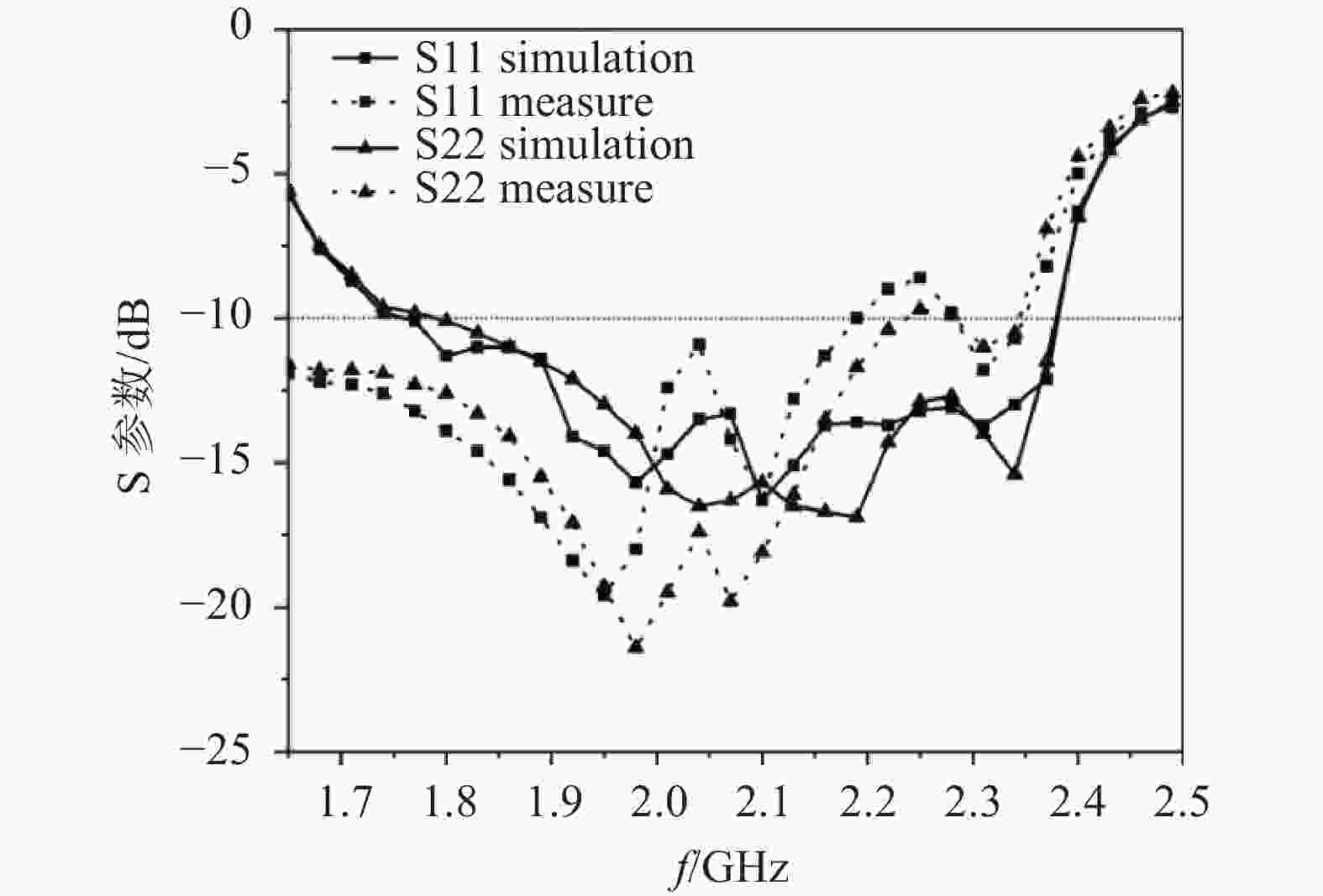
图 4 天线的S参数
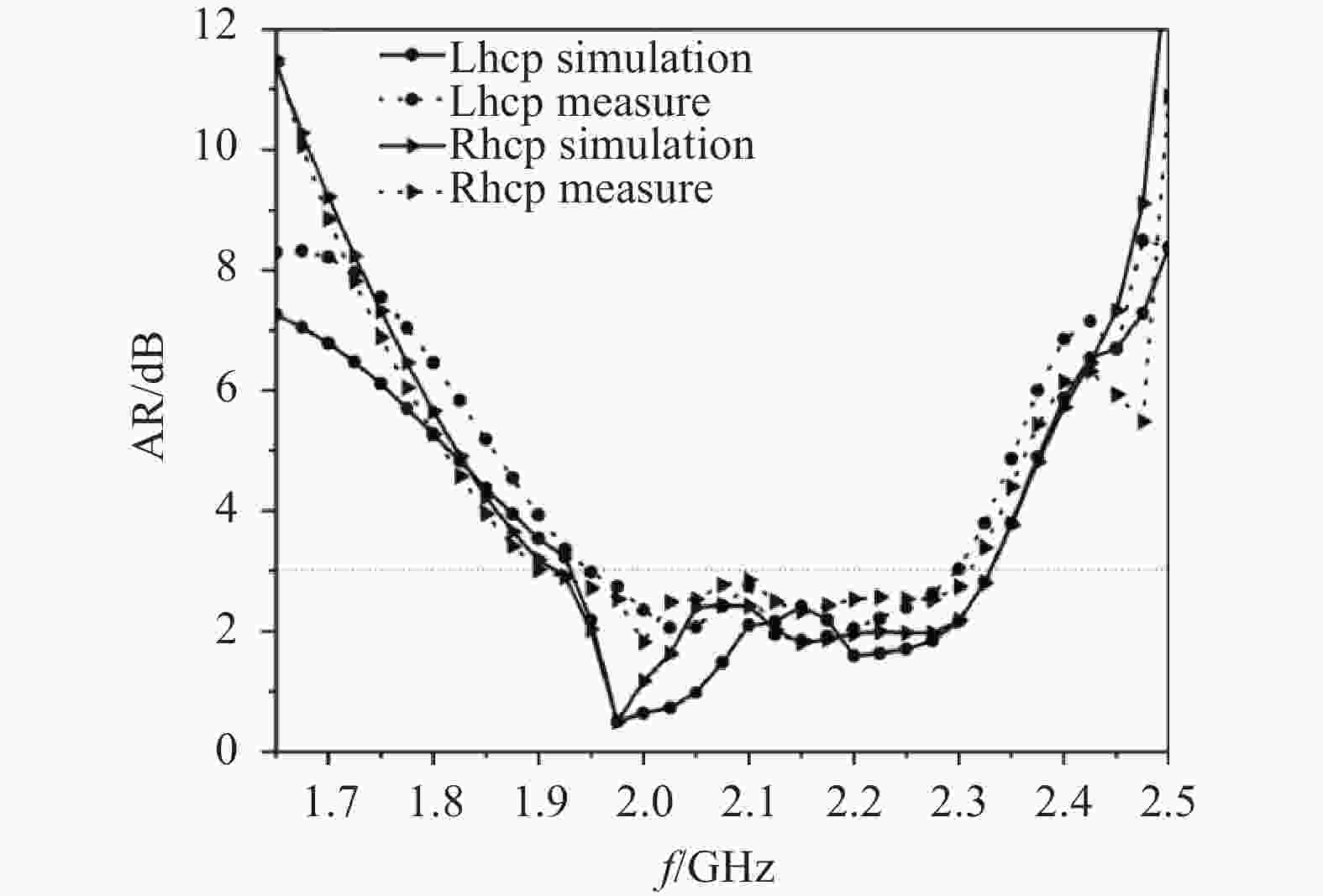
图 5 天线的轴比(法向)
-
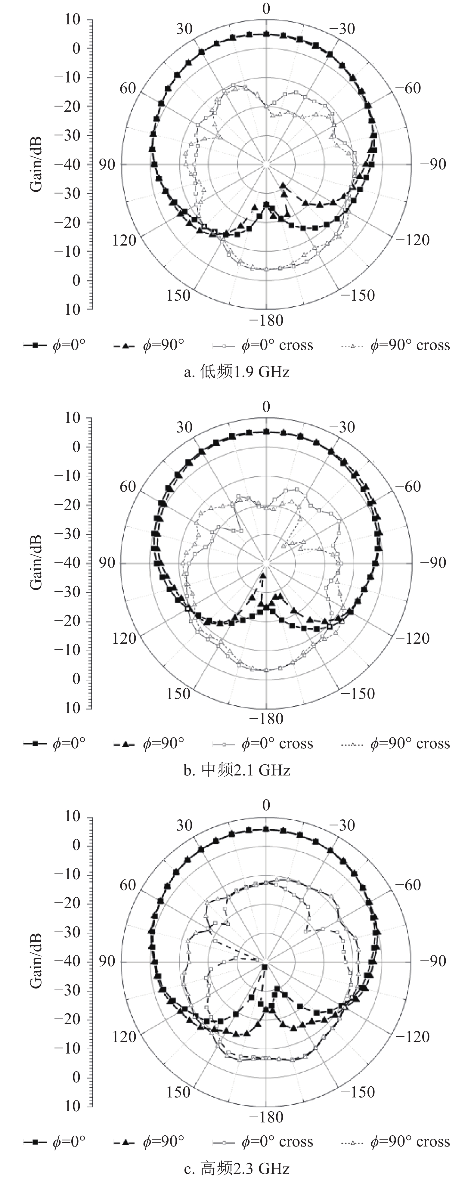
图6为天线的方向图。由图6可以看出,天线左旋圆极化方向图的E面和H面一致性较好,右旋结果类似。天线的半功率波束宽度大于110°(−55°~55°),天线的交叉极化抑制度优于20 dB。

图 6 天线的方向图(左旋)
-
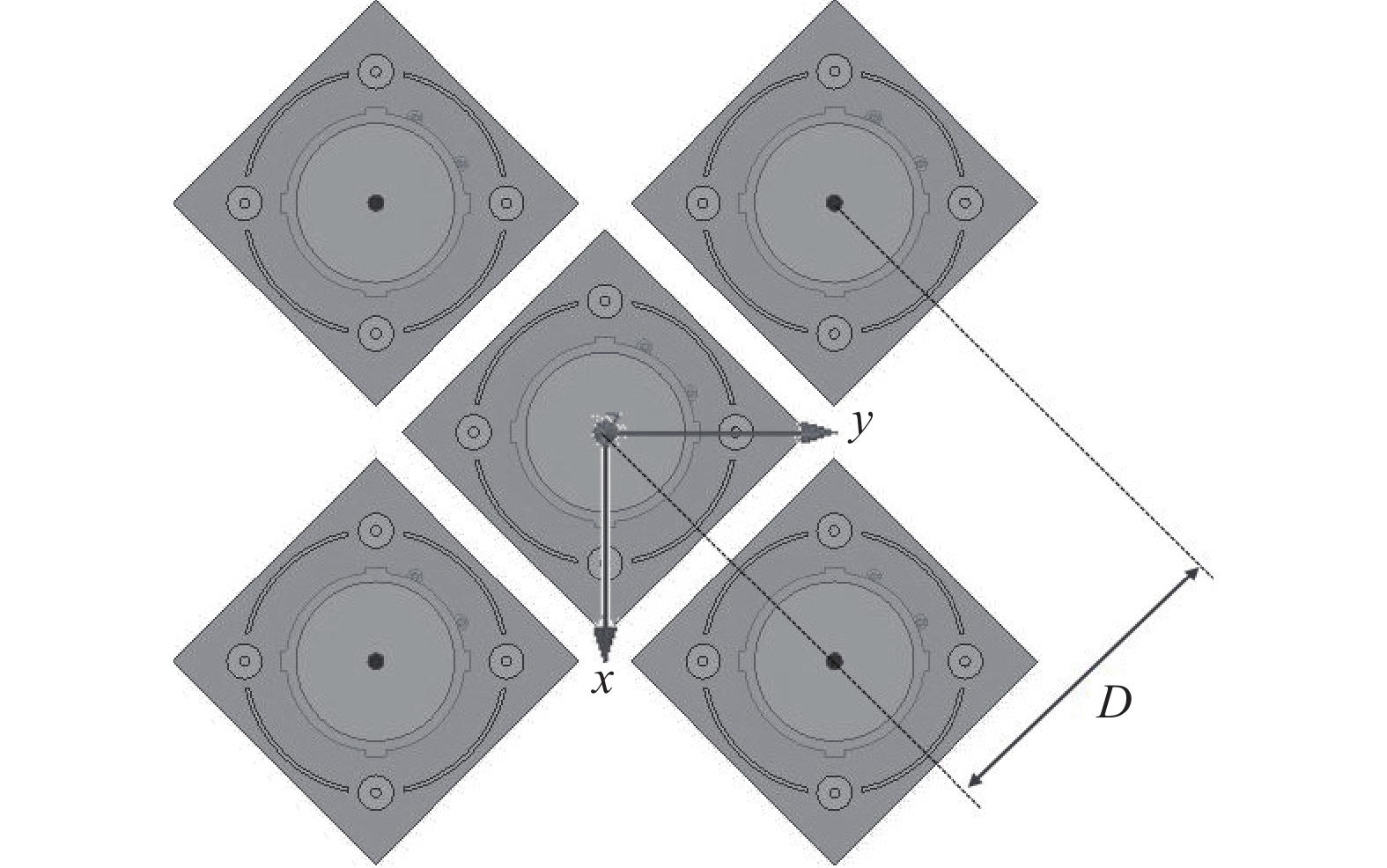
为了避免出现栅瓣,单元间距应不大于半波长。将5个单元按相同的距离排成如图7所示的面阵,其中距离D=65 mm,阵列的总尺寸是180 mm×180 mm×8 mm。
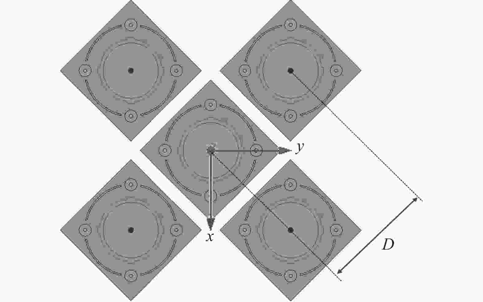
图 7 阵列天线布局图
-
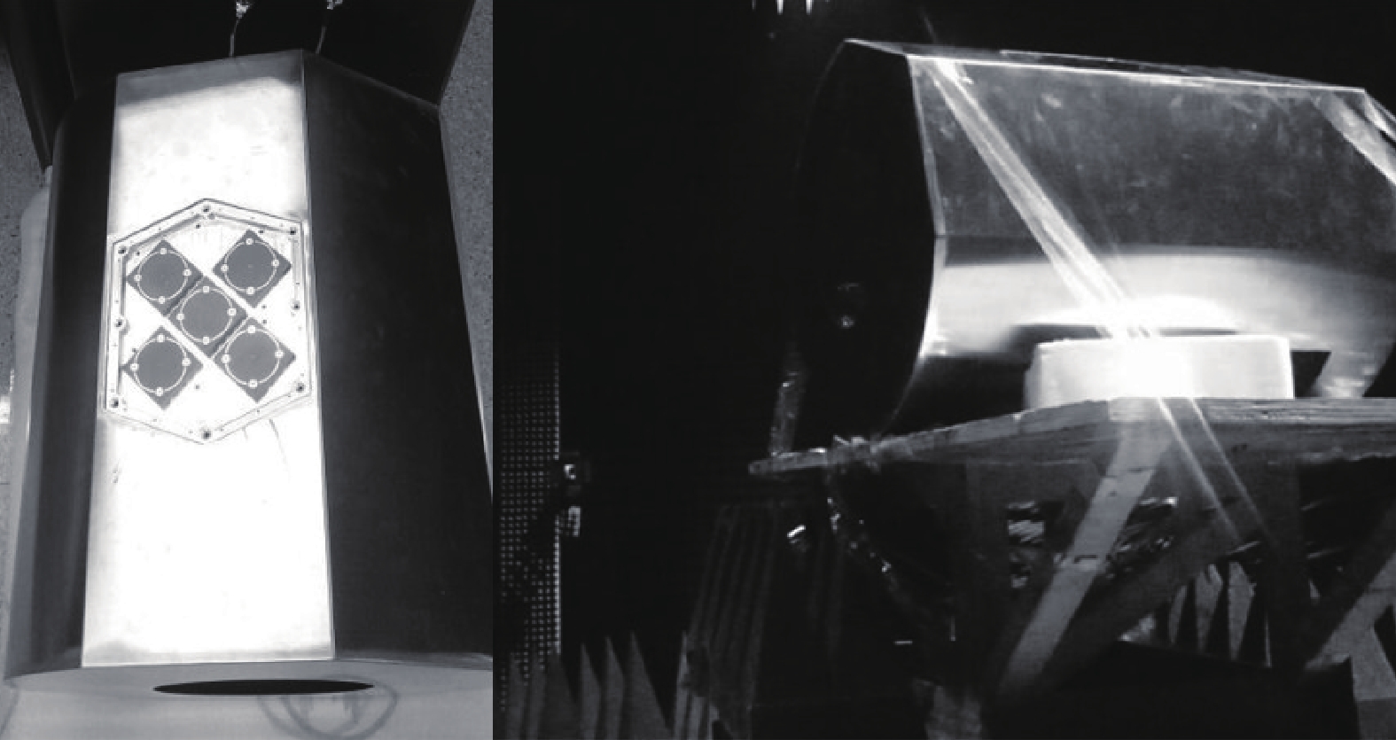
图8为天线实物和暗室测试情况,五阵元天线阵安装在模拟实际应用的天线载体上。天线及其载体在仿真和加工过程中充分考虑了加工可实现性和一致性,有效地提高了仿真与实测的准确性。

图 8 天线阵列在暗室中的测试图
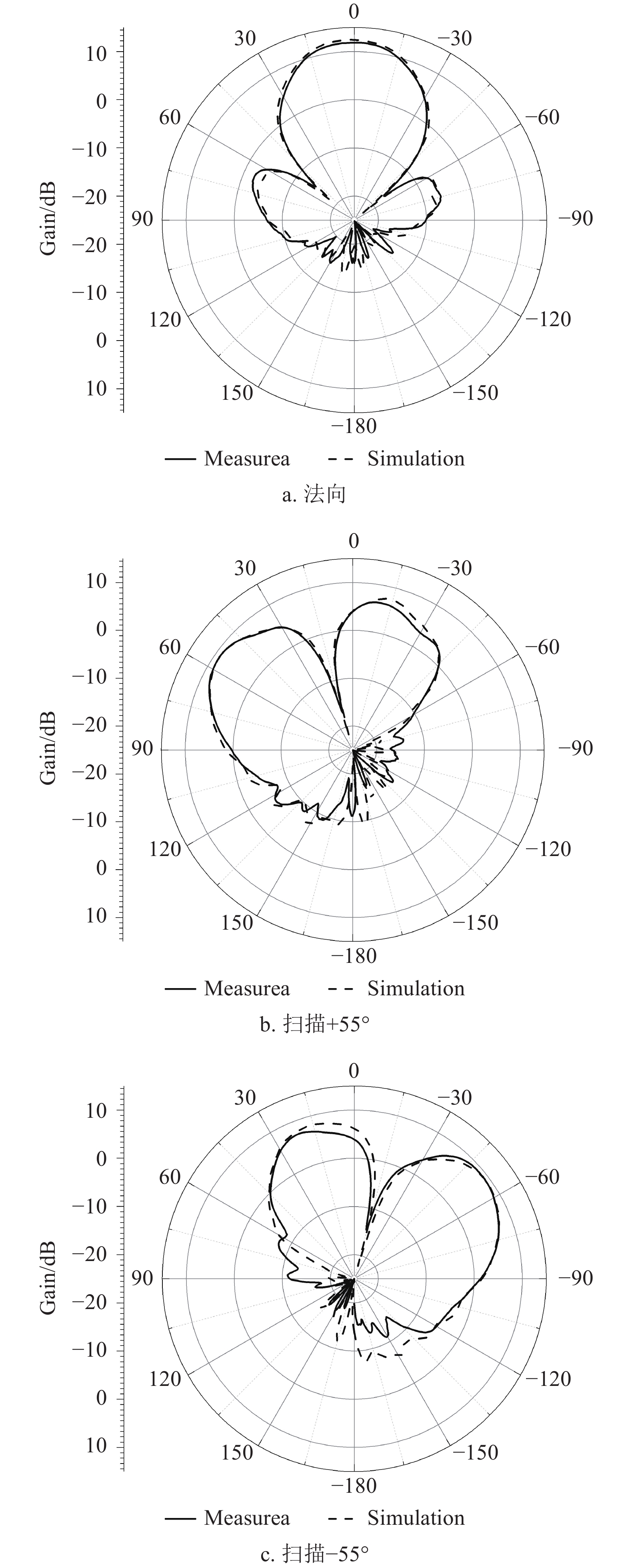
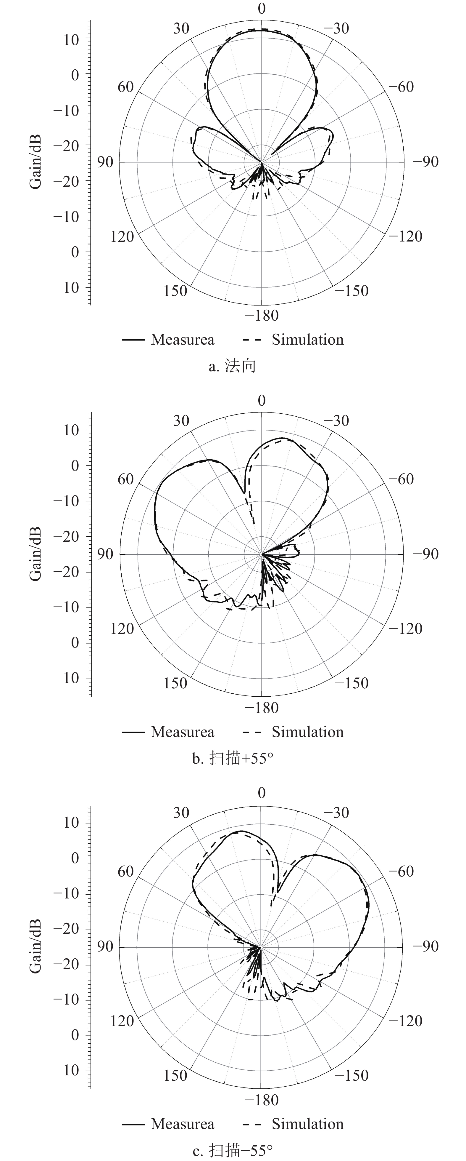
天线阵列的方向图测试结果如图9和图10所示,方向图法向增益和副瓣值如表2所示,方向图大角度扫描结果如表3所示,实际应用中大角度扫描时对高副瓣指标不做要求。由结果看出,仿真与实测结果一致性较高。
表 2 阵列天线的法向增益及副瓣电平
频率/GHz Gain/dBi SLL/dB 实测值 仿真值 实测值 仿真值 2.1 11.8 12.4 −15.6 −16.4 2.3 12 12.5 −16.1 −16.9 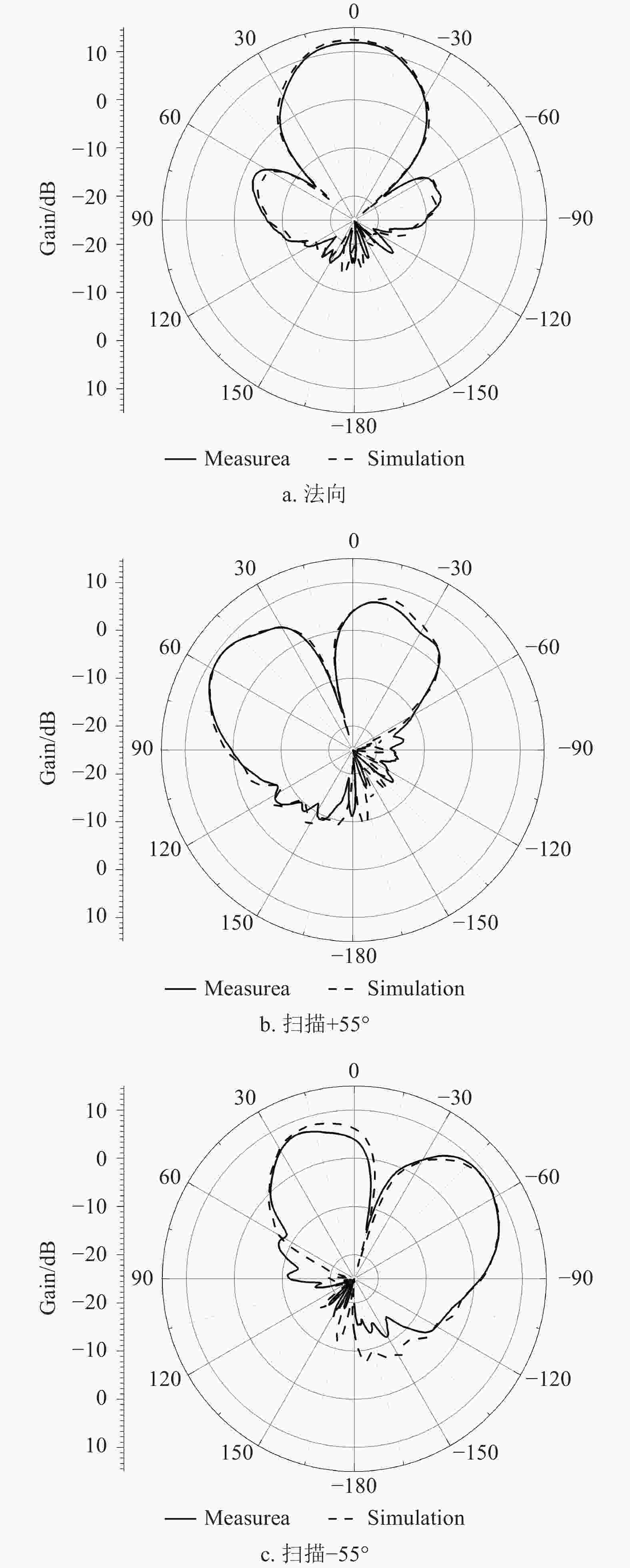
图 9 左旋2.1 GHz处天线阵列方向图
表 3 阵列天线的扫描增益
频率/GHz Gain/dBi 扫描+55° 扫描−55° 实测值 仿真值 实测值 仿真值 2.1 9.0 9.1 9.1 9.4 2.3 9.4 9.5 9.2 9.3 
图 10 右旋2.3 GHz处天线阵列方向图
-
本文设计了一款双馈双圆极化宽带层叠微带天线,并对该天线的工作机理进行了分析,通过仿真分析和加工实测,验证了该天线具有宽带宽波束、交叉极化抑制度高等诸多优点。为了进一步发挥天线的优势,设计了非规则五单元阵列,测试结果表明该阵列保持了良好的辐射特性。
A Double Circular Polarization Broadband Antenna and Its Array Applications
-
摘要: 该文设计了一种双圆极化宽带天线单元,并在此基础上实现了小型阵列天线。单元天线为层叠型微带天线,其辐射贴片的四周寄生了环形金属带和金属柱以拓展波束宽度。另外,为了满足双圆极化要求和拓展天线带宽,天线采用电桥进行馈电。天线单元的10 dB阻抗带宽为26.9%(1.8~2.36 GHz),3 dB轴比带宽为19.3%(1.92~2.33 GHz),方向图半功率波束宽度大于110°。对非规则的五单元面阵进行了研究。测试结果表明,该天线阵的合成增益高于11.5 dBi,±55°扫描增益高于9 dBi,仿真和实验结果一致性较高,为宽带卫星通信的应用奠定了基础。Abstract: A double circular polarization broadband antenna is designed, and a small array is realized on this basis. The element antenna is a stacked microstrip antenna with a ring of metal bands and metal columns around the radiation patch to expand the beam width. In addition, in order to meet the requirements of double circular polarization and to expand the antenna bandwidth, the antenna is fed by a ring bridge. The 10 dB impedance bandwidth is 26.9% (1.8 GHz~2.36 GHz), the 3 dB axial ratio bandwidth is 19.3% (1.92~2.33 GHz), and the 3 dB beam width is greater than 110°. A non-regular five elements array is investigated. The test results show that the synthetic gain is higher than 11.5dBi, and the ±55° scanning gain is higher than 9dBi. The simulation and experimental results are consistent, which is the foundation of broadband satellite communication application.
-
Key words:
- broadband /
- double circular polarization /
- doubly-fed /
- stacked patch antenna /
- wide beam
-
表 1 天线的详细尺寸
mm 参数 取值 参数 取值 WS 58 LS 58 r1 16.6 rc 3.6 r2 15.6 rm 1.5 rf 10.5 wc 0.83 rb 25.9 wf 0.87  下载: 导出CSV
表 2 阵列天线的法向增益及副瓣电平
频率/GHz Gain/dBi SLL/dB 实测值 仿真值 实测值 仿真值 2.1 11.8 12.4 −15.6 −16.4 2.3 12 12.5 −16.1 −16.9
下载: 导出CSV
表 3 阵列天线的扫描增益
频率/GHz Gain/dBi 扫描+55° 扫描−55° 实测值 仿真值 实测值 仿真值 2.1 9.0 9.1 9.1 9.4 2.3 9.4 9.5 9.2 9.3
下载: 导出CSV
-
[1] DUBROVKA F F, MARTYNYK S Y. Wideband dual polarized planar antenna arrays[C]//International Conference on Antenna Theory and Techniques. [S.l.]: IEEE, 2003: 91-96. [2] YUN W, YOON Y J. A wide-band aperture coupled microstrip array antenna using inverted feeding structures[J]. IEEE Transactions on Antennas & Propagation, 2005, 53(2): 861-862. [3] GAO S, VAHLDIECK R, SAMBELL A. Broadband dual-polarized antenna for active array applications[J]. Antennas and Propagation Society International Symposium, 2004, 4: 3919-3922. [4] BAUERLE R J, GOTHARD G, VERGAMINI A. A center fed multi-band antenna for simultaneous satellite communication at C and Ku bands[C]//Military Communications Conference. [S.l.]: IEEE, 2010: 1564-1571. [5] SCHIPPERS H, VERPOORTE J, JORNA P. Development of dual-frequency airborne Satcom antenna with optical beamforming[C]//Aerospace Conference. [S.l.]: IEEE, 2009: 1-16. [6] ERDEMLI Y E, GILBERT R A, VOLAKIS J L. A reconfigurable slot aperture design over a broad-band substrate/feed structure[J]. IEEE Transactions on Antennas & Propagation, 2004, 52(2): 2860-2870. [7] SHAVIT R, PAZIN L, ISRAELI Y, et al. Dual frequency and dualcircular polarization microstrip nonresonant array pin-fed from a radialline[J]. IEEE Transactions on Antennas & Propagation, 2005, 53(12): 3897-3905. doi: 10.1109/TAP.2005.859911 [8] SMOLDERS A B, MESTROM R M C, RENIERS A C F, et al. A shared aperture dual-frequency circularly polarized microstrip array antenna[J]. IEEE Antennas & Wireless Propagation Letters, 2013, 12(1921): 120-123. [9] GHORBANI K, WATERHOUSE R B. Dual polarized wide-band aperture stacked patch antennas[J]. IEEE Transactions on Antennas & Propagation, 2004, 52(8): 2171-2175. [10] REN Jie, ZHANG Li-na, LIANG Xian-ling, et al. A wideband and wide-angle scanning circularly polarized array with low profile[C]//2017 IEEE International Symposium on Antennas and Propagation & USNC/URSI National Radio Science Meeting. [S.l.]: IEEE, 2017, DOI: 10.1109/APUSNCURSINRSM.2017.8072950. [11] LIANG Xian-ling, REN Jie, ZHANG Li-na, et al. Wideband circularly polarized antenna with dual-mode operation[J]. IEEE Antennas and Wireless Propagation Letters, 2019, DOI: 10.1109/LAWP.2019.2902257. -

 点击查看大图
图(10) / 表(3)
计量
- 文章访问数: 7163
- HTML全文浏览量: 2539
- PDF下载量: 67
- 被引次数: 0