ISSN
ISSN 


 下载:
下载:


-
Thin-walled plates and shells have been extensively used in civil, automotive, aerospace and many other disciplines because of their outstanding designability, high stiffness-to-weight ratio and excellent strength-to-weight ratio[1-3]. However, in practical applications, the actual usage lifetime of a number of these components is much shortened due to their sensitivity to the unavoidable imperfections, microcracks, accumulated damage in service and so forth. It is of particular importance to understand the physical essence of fatigue crack initiation and growth process inside such structures and to accurately predict their fatigue life so as to realize safe applications and prevent catastrophic accidents.
Up to now, various experimental, theoretical, and numerical works[4-15] have been conducted in this aspect, while quantifying the crack growth behavior together with the service lifetime of actual thin-walled structures is still a challenging problem for mechanics theories and engineering applications. In this study, our attention is mainly focused on the simulation of NFCG process of thin-walled plates and predicting their fatigue life under various cyclic loading conditions in the scaled boundary finite element method (SBFEM) framework.
Different from the finite element method (FEM), extended finite element method and meshfree method[12, 14-17], SBFEM is a semi-analytical approach combining the advantages of specificly FEM and the boundary element method. The finite element discretization is employed along the circumferential direction parallel to the external boundary of a certain domain. Then, the governing partial differential equations of boundary value problem (BVP) are transformed into a set of ordinary differential equations with the radial coordinate as the independent variable. Hence, the resulting physical fields along the radial direction are analytical, while those in the circumferential direction are numerical. Further, the mesh generation efficiency of complex structures is substanntially improved with greatly reduced unknown numbers, as only the external boundary necessitate being discretized. Therefore, these merits make the SBFEM a promising strategy in modelling singularity ascribed to cracks[18], analyzing damage in huge structures[19], reliability analysis[20] and so forth.
SBFEM was first developed by Wolf and Song[21] to deal with the unbounded BVPs, and its theoretical foundation was further enriched.[10, 11, 18, 22]. Afterwards, this method was extended to evaluating the stress intensity factor (SIF), cohesive effect, interactions and T-stress around the crack tip inside homogeneous materials or between two dissimilar materials[20, 23-26], to solve couple-field problems[27-30], and construct polygon elements[13, 31-33]. However, quite a few works[13, 34] have been conducted so far on predicting the fatigue lifetime of thin-walled plates taking account of the integrated effects of cyclic loading conditions and specimen characteristics in the framework of SBFEM. Hence, this work aims to fill in this gap, and elaborate a computational scheme to simulate the NFCG phenomenon with SBFEM and predict the fatigue lifetime of specimen with different thicknesses under various cyclic loading conditions.
The structure of this paper is organized as follows. A NFCG model is first introduced to account for the combined effect of the loading conditions and the specimen characteristics. Hereafter, the governing formulations of SBFEM is briefly invoked and a computational strategy is developed to simulate the NFCG process and to predict the fatigue lifetime of thin-walled plates. The simulation scheme is summarized as a flow chart to clearly illustrate the whole process.
-
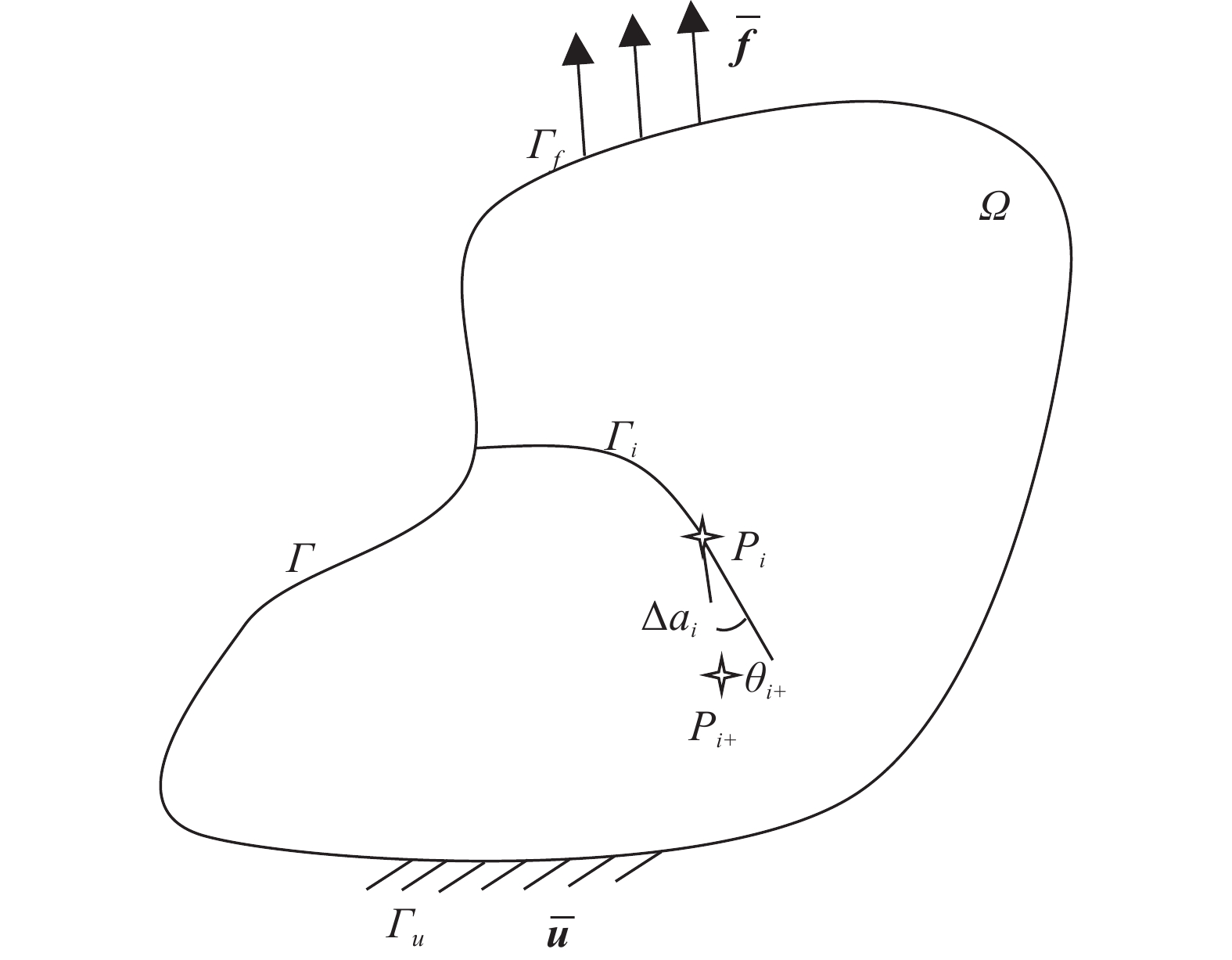
Here, we consider a 2D continum structure Ω bounded by the external boundary Γ shown in Fig. 1 as an illustration, and the boundary conditions are given as
$$ \left\{ \begin{array}{l} { u} = \overline {{ u}}\;\;\;\quad{\varGamma _u} \\ { f} = \overline {{ f}} \;\;\;\quad{\varGamma _f} \\ \end{array} \right. $$ (1) where
$\overline { u} $ and$\overline { f} $ refers to the displacement and normal traction vectors imposed on Γu and Γf, respectively. A natural fatigue crack denoted by Γc is embedded in Ω, and the position of the crack tip after the i-th loading cycle with i ≥1 is at the point Pi. During the (i+1)-th loading cycle, the crack Γc propagates in Ω with the length Δai+1 and the directional ange θi+1, and the crack tip moves to Pi+1.
Figure 1. A 2D continum plate containing one edge crack
Experimental observations[4, 5, 16, 34-36] indicate that the fatigue crack growth in practical components is affected by various factors, including the loading sequence and ratios, microdefects, specimen geometry, material properties and so forth. Many NFCG models[6-8, 37-40] have been proposed thus far. In this study, the following NFCG model is adopted to characterize the fatigue crack growth rates of the whole process[8, 39].
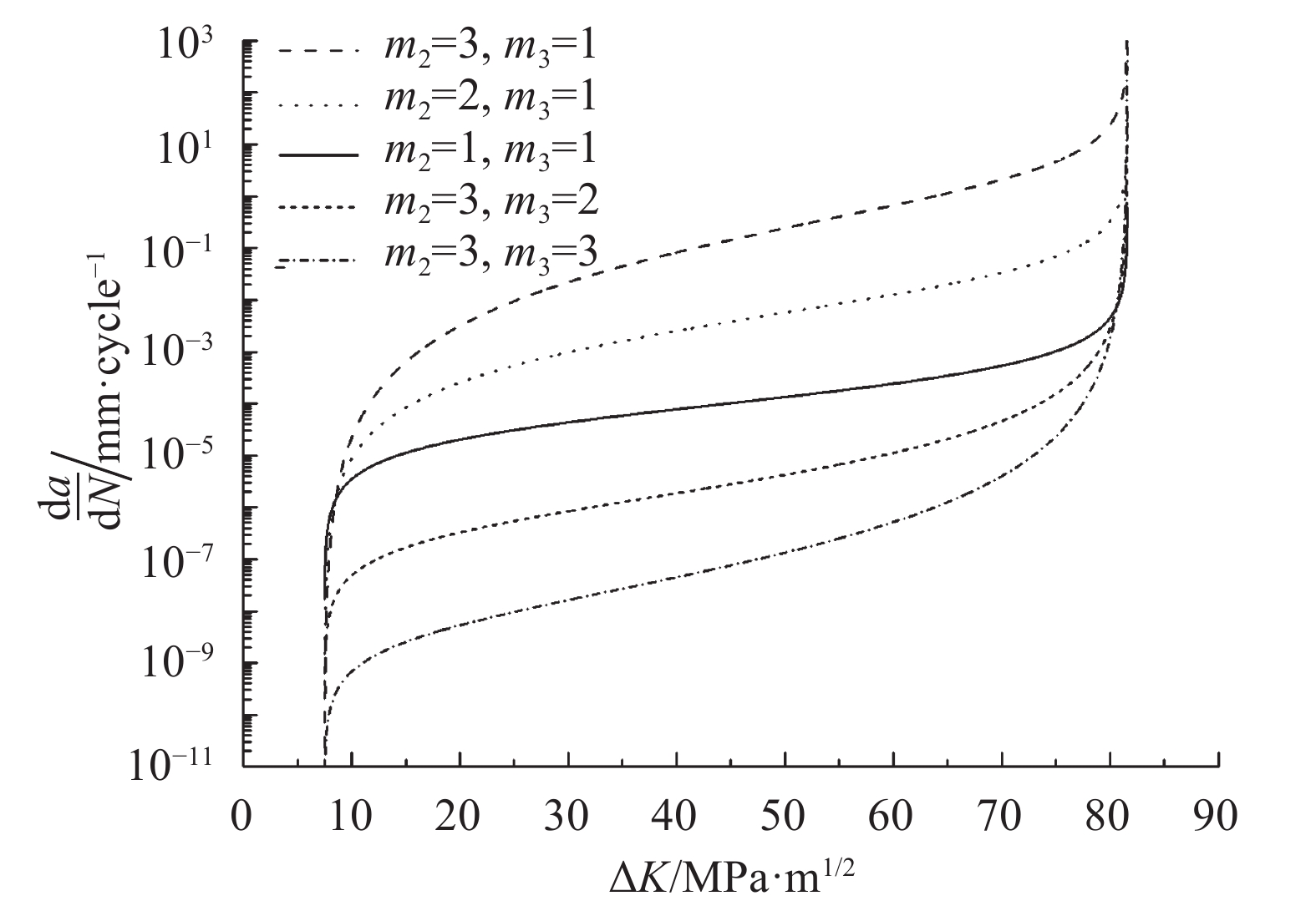
$$ \frac{{{\rm d}a}}{{{\rm d}N}} = {c_1}{\left( {U \Delta K} \right)^{{m_1}}}\frac{{{{\left( {\Delta K - \Delta {K_{{\rm{th}}}}} \right)}^{{m_2}}}}}{{{{\left[ {\left( {1 - R} \right){K_{{\rm{IC}}}} - \Delta K} \right]}^{{m_3}}}}} $$ (2) where c1 and m1~m3 are the model coefficients to be determined based on the experimental data. Physically, m2 and m3 determine the manner of da/dN approaching the cracking threshold ΔKth and the material fracture roughness KIC in Fig. 2, respectively. ΔK denotes the variation of the stress intensity factor (SIF), and R is the cyclic stress ratio.

Figure 2. Influence of the model coefficients m2 and m3 on da/dN
In Eq. (2), U refers to the effective stress intensity factor range ratio defined by
$$ U = \left\{\!\!\!\!\! {\begin{array}{*{20}{c}} {\dfrac{{1 - \gamma }}{{1 - R}}\begin{array}{*{20}{c}} {}&{\gamma \leqslant 1} \end{array}} \\ {0\begin{array}{*{20}{c}} {}&{}&\;\;\;\;{\gamma > 1} \end{array}} \end{array}} \right. $$ (3) where γ is the crack opening ratio. To properly describe the combined effect ascribed to the loading conditions and the specimen characteristics, γ is defined in this study as[8, 41]
$$ \gamma = \left\{ \begin{split} & {{A_0} + {A_1}R + {A_2}{R^2} + {A_3}{R^3}}\quad\;\; {R \geqslant 0} \\ & {{A_0} + {A_1}R}\quad\qquad\qquad { - 1 \leqslant R < 0} \end{split}\right. $$ (4) The coefficients A0~A3 are evaluated by
$$ \begin{split} {A_0} =& (0.825 - 0.34\beta + 0.05{\beta ^2}){\left[ {\cos \left( {\frac{{\text π} }{2}\frac{{{S_{\max }}}}{{{\sigma _{{f}}}}}} \right)} \right]^{1/\beta }}\\ & {A_1} = \left( {0.415 - 0.071\beta } \right)\frac{{{S_{\max }}}}{{{\sigma _{{f}}}}}\\ & {A_2} = 1 - {A_0} - {A_1} - {A_3}\\ & {A_3} = 2{A_0} + {A_1} - 1\\ & \beta = \frac{{{\beta _{{\rm{sa}}}} - {\beta _{{\rm{ss}}}}}}{{1 + {{\left( {1.4{t_{{\rm{re}}}}} \right)}^{2.15}}}} + {\beta _{{\rm{ss}}}}\\ & {\beta _{{\rm{ss}}}} = \frac{1}{{11.41 - 31.22v}}\\ & {\beta _{{\rm{sa}}}} = \frac{1}{{1.39 - 3.16v}} \end{split} $$ (5) with v the material Poisson’s ratio and tre the relative thickness of thin-walled plates expressed as
$$ {t_{{\rm{re}}}} = c{\left( {{k_{{\rm{mat}}}}{S_{\max }}} \right)^2}/\left( {t\sigma _{{f}}^{\rm{2}}} \right) $$ (6) where c is a material-property-related constant, t is the specimen thickness and kmat is defined as
$$ {k_{{\rm{mat}}}} = {\sigma _{{f}}}/{\sigma _{{s}}} $$ (7) where σf is the material flow stress, and σs is the material yielding stress.
Then, the foregoing fatigue crack propagation length Δai+1 can be explicitly expressed as
$$ \Delta {a_i}_{ + {\rm{1}}} = {c_1}{\left( {U \Delta {K_{i{\rm{ + 1}}}}} \right)^{{m_1}}}\frac{{{{\left( {\Delta {K_{i + {\rm{1}}}} - \Delta {K_{{\rm{th}}}}} \right)}^{{m_2}}}}}{{{{\left[ {\left( {1 - R} \right){K_{{\rm{IC}}}} - \Delta {K_{i{\rm{ + 1}}}}} \right]}^{{m_3}}}}} $$ (8) where ΔKi represents the variation of the mixed-mode SIF[42] of the (i+1)-th cycle, and is further written as
$$ \Delta {K_{i{\rm{ + 1}}}} = \sqrt[{\rm{4}}]{{\Delta K_{{\rm I},(i{\rm{ + 1)}}}^{\rm{4}} + {\rm{8}}\Delta K_{{\rm {II}},(i{\rm{ + 1)}}}^{\rm{4}}}} $$ (9) with
$\Delta {K_{{\rm I},(i{\rm{ + 1)}}}}$ and$\Delta {K_{{\rm {II}},(i{\rm{ + 1)}}}}$ the variation of the mode-I and mode-II SIFs, respectively.In this study, the maximum circumferential stress criterion[43] is adopted to characterize the fatigue crack growth direction
$$ {\theta _{\rm{c}}} = - \arccos \left( {\frac{{{\rm{2}}K_{{\rm{II}}}^{\rm{2}} + {K_{\rm{I}}}\sqrt {K_{\rm{I}}^{\rm{2}} + {\rm{8}}K_{{\rm{II}}}^{\rm{2}}} }}{{K_{\rm{I}}^{\rm{2}} + {\rm{9}}K_{{\rm{II}}}^{\rm{2}}}}} \right) $$ (10) Here, we assume that the fatigue cracks under consideration propagate along a straight line within one loading cycle. Combining (3)~ (10), we can quantitatively determine the directional FCG velocities, the cracking direction and the location of the newly-formed crack tip Pi+1.
It is noted that the foregoing NFCG model takes explicitly account of the influence of the loading conditions by (3), the material property and specimen geometry effects by (2), (6) and (7), and the cracking physics near ΔKth and KIC. Hence, it is of great convenience in applying this model for specimen design, material selection, and NFCG rate and fatigue lifetime estimation in practical applications. In the following sections, the NFCG model in Eqs. (1)~(10) will be numerically implemented in the SBFEM context.
-
As stated previously, SBFEM shows various advantages over other strategies in simulating natural fatigue crack growth and in predicting fatigue lives due to its accurate description of SIFs at the crack tip, fewer DOFs are needed for simulation and analytical physical fields along the radial direction. In this section, a computational scheme is developed using SBFEM to simulate the NFCG process of 2D thin-walled structures.
-
For brevity, the 2D continum in Fig. 1 is taken again as an example. Here, the quasi-static elastic problem is addressed, and the body force of Ω is assumed to be negligible. Thus, the equilibrium equation of a point x in Ω is written as
$$ {{{L}}^{\rm{T}}}{{\sigma }}\left( {{x}} \right) = 0 $$ (11) with σ=[σxx, σyy, σxy]T being the stress vector and
$$ {{{L}}^{\rm{T}}} = \left[ {\begin{split} & {\frac{\partial}{{\partial x}}}\quad 0\quad {\frac{\partial }{{\partial y}}} \\ & 0\quad {\frac{\partial }{{\partial y}}}\quad {\frac{\partial }{{\partial x}}} \end{split}} \right] $$ (12) The stress vector σ at the point x is related to the strain vector ε= [εxx, εyy, εxy]T by
$$ {{\sigma }}\left( {{x}} \right) = {{D}} {{\varepsilon }}\left( {{x}} \right) $$ (13) where D is the second-order elastic matrix of the material forming Ω.
The strain vector ε can be rewritten in terms of the displacement vector u=[ux,uy]T as
$$ {{\varepsilon }}\left( {{x}} \right) = {{L}} {{u}}\left( {{x}} \right) $$ (14) The displacement u and traction f satisfy the relations presented in Eq. (1) on the external boundary Γ and fulfill the formula below on the cracking surface Γi:
$$ {{f}} = \left\{ {\begin{split} & 0\qquad\qquad\quad{{\rm{Crack}}\;{\rm{opens}}} \\ & {{\rm{continuous}}}\quad{{\rm{Crack}}\;{\rm{closes}}} \end{split}} \right. $$ (15) Equations (11)~(15) together with (1) constitute the strong governing formulation of the boundary value problem in Fig. 1. Then, the weak governing equation of the BVP in Fig. 1 is derived by using the virtual work theorem[22] or the weighted residual formulation[10, 11] as
$$ \int\limits_V {\delta {{{\varepsilon }}^{\rm{T}}}\left( {{x}} \right) {{\sigma }}\left( {{x}} \right)} {\rm{d}}V - \int\limits_\Gamma {\delta {{{u}}^{\rm{T}}}\left( {{{{x}}_s}} \right) {{t}}\left( {{{{x}}_s}} \right)} {\rm{d}}S = {\rm{0}} $$ (16) where xs refer to the points on the boundary Г.
Then, the whole domain Ω is discretized into polygon elements of any number of sides, e.g. Fig. 3. Simultaneously, a scaling center (e.g. O(i)) is defined for each element and specifically, the whole boundary of the element is visible from its scaling center. A local polar coordinate system is defined such that the radial axis ξ directs from the scaling center O(i) towards the element boundary, and its value is 0 at the scaling centre and is 1 at the element boundary; the circumferential axis is denoted as η and physically represents the distance between a particular point and the origin point selected on the element boundary.
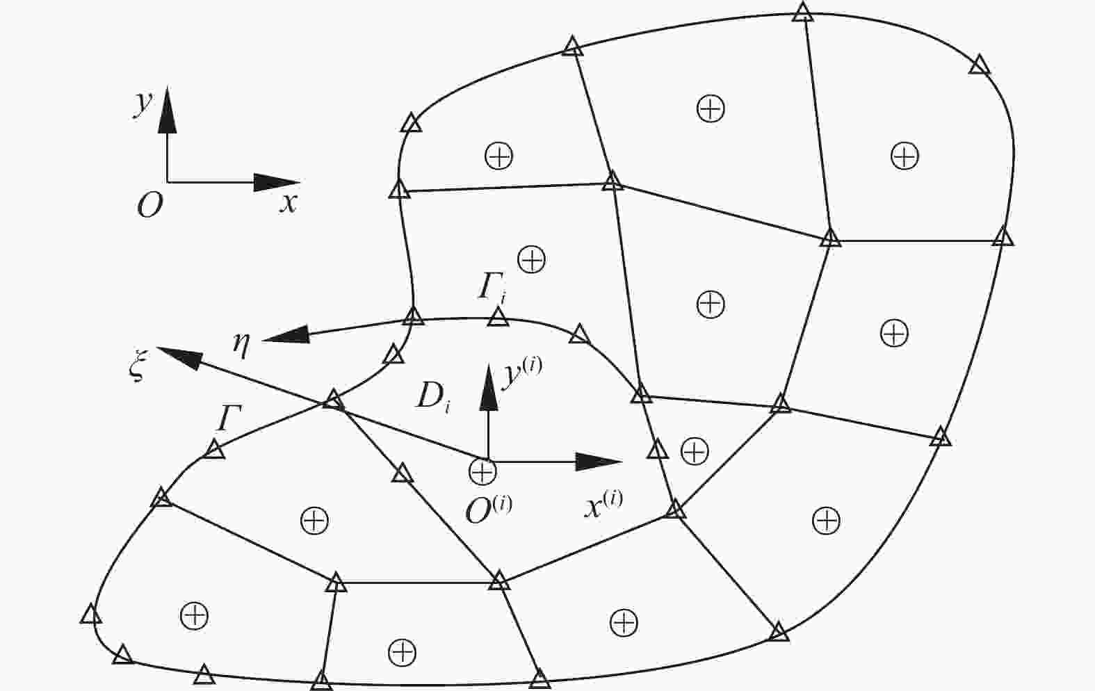
Figure 3. Continua discretized by SBFEM
Accordingly, the displacement vector of any point (ξ, η) in the i-th subdomain Di can be explicitly approximated by
$$ {{u}}(\xi ,\eta ) = \sum\limits_{k = {\rm{1}}}^{{m_i}} {{N_k}\left( \eta \right){{{u}}_k}\left( \xi \right)} $$ (17) where mi denotes the total number of nodes on external boundary of Di; Nk(η) is the shape function associated with the k-th node and related to the circumferential coordinate merely; uk(ξ) is the radial displacement function associated with the k-th boundary node and defined by[10, 11, 22]
$$ {{{u}}_k}\left( \xi \right) = \sum\limits_{j = {\rm{1}}}^\iota {{c_{k\_j}}{\xi ^{{\lambda _j}}}{{{\varphi }}_{k\_j}}} $$ (18) where ck_j is the boundary condition dependent constant and physically represent the contribution of each mode to the final solution; λj and φk_j are the positive eigenvalues and the associated eigenvectors of a standard eigenproblem[43] and satisfy the internal equilibrium along the ξ direction[42].
Combining Eqs. (12)~(18) and assembling the stiffness matrix and the loadings of all polygon subdomains together following the procedure presented in Refs.[22, 43], we finally obtain the equilibrium equation of the aforementioned BVP:
$${{K}} {{d}} = {{F}}$$ (19) where K is the global stiffness matrix related to the geometry and the material of the BVP in question, d contains all unknows at the nodes, and F is the global external force vector.
Solving Eq. (19) delivers the nodal displacements on the element boundary. Then, invoking the relations in Eqs. (17) and (18), we can determine the resulting displacement and stress of any point in the domain by
$$ \begin{split} &\qquad\quad{{u}}(\xi ,\eta ) = \sum\limits_{k = {\rm{1}}}^{{m_i}} {{N_k}\left( \eta \right)\left( {\sum\limits_{j = {\rm{1}}}^\iota {{c_{k\_j}}{\xi ^{{\lambda _j}}}{{{\varphi }}_{k\_j}}} } \right)} \\ &{{\sigma }}(\xi ,\eta ) = {{D}}\left( {\sum\limits_{j = {\rm{1}}}^\iota {{c_{k\_j}}{\xi ^{{\lambda _j}{\rm{ - 1}}}}\left[ {{\lambda _j}{{{B}}^{\rm{1}}}\left( \eta \right) + {{{B}}^{\rm{2}}}\left( \eta \right)} \right]{{{\varphi }}_{k\_j}}} } \right) \end{split} $$ (20) where B1(η) and B2(η) are the strain-displacement matrices[22, 43]. Note that these two matrice are functions of the circumferential coordinate η only, which indicates that the displacement and stress solutions by SBFEM are analytical along the radial direction ξ.
Practically, the propagation direction of natural fatigue cracks is largely influenced by the external loadings, the material property, the geometry of the structures, and the local defects. Fig. 4 visualizes the schematic diagram of a generic cracked body modelled by the SBFEM. To evaluate the SIFs of cracks of this kind, the Williams eigenfunction expansion around the crack tip[24, 42] is first applied and the stresses of the point Q at the crack surface direction on the element boundary as Fig. 4 in the global. Cartesian coordinate system are then transformed to the normal stress σn (mode I) and the shear stress τn (mode II) defined on the cracking sruface plane. Finally, the mixed model SIFs are determined by
$$ \left[ {\begin{array}{*{20}{c}} {{K_{\rm{I}}}} \\ {{K_{{\rm{II}}}}} \end{array}} \right] = \sqrt {{\rm{2}}{\text π} {L_0}} \sum\limits_{i = {\rm{I,II}}} {\left( {{c_i}\left[ {\begin{array}{*{20}{c}} {{\sigma _n}\left( {{\eta _Q}} \right)} \\ {{\tau _n}\left( {{\eta _Q}} \right)} \end{array}} \right]} \right)} $$ (21) where L0 is the distance between the crack tip and the point Q whose location doesn’t necessarily coincide any existing node. The stresses of Q can be conveniently recovered by using Eq. (20).
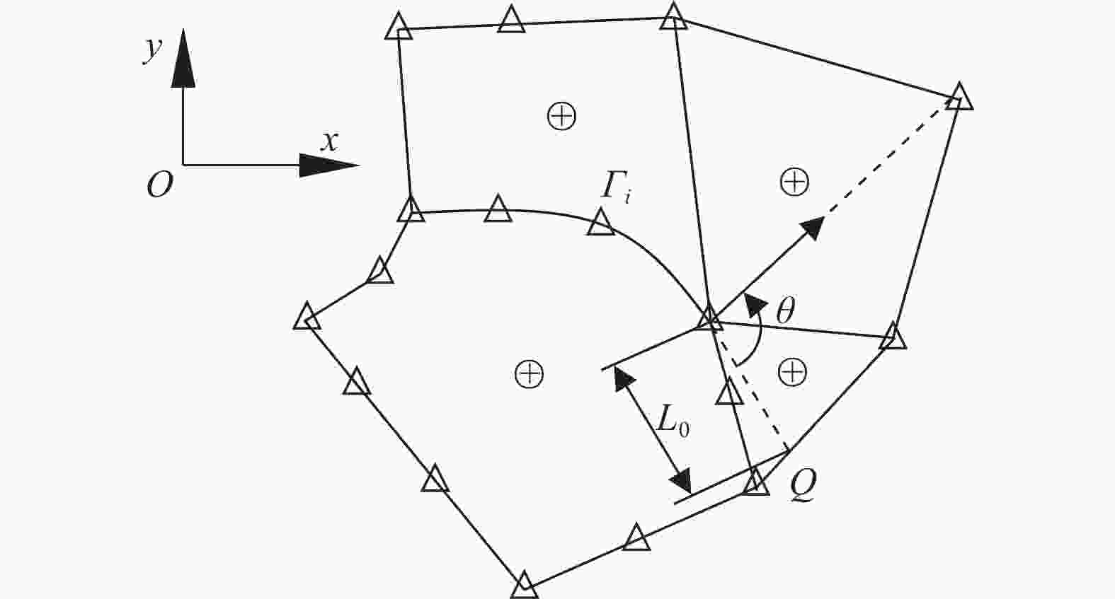
Figure 4. Schematic diagram to evaluate the SIF of a generic cracked body
-
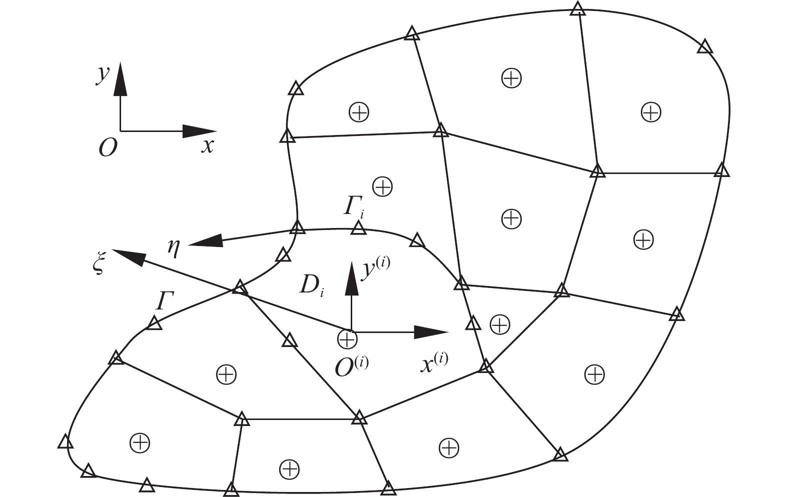
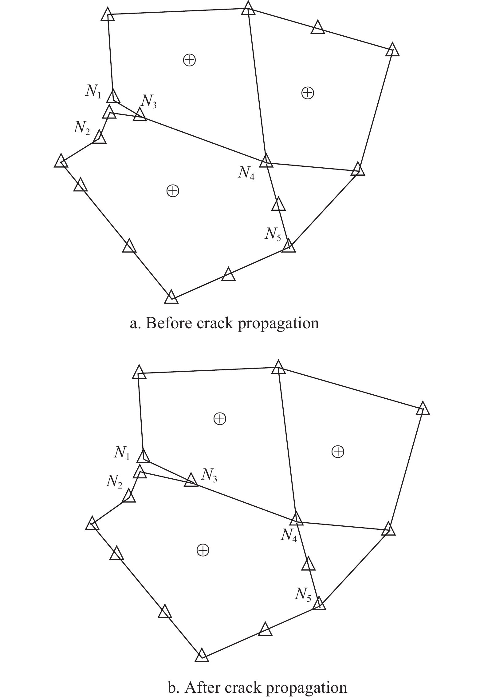
From many literatures[6-8, 37-41] and experimental observations, it is known that the NFCG includes three typical stages shown in Fig. 2. The slow growth stage near the cracking threshold ΔKth (Stage I), the steady growth stage (Stage II) and the fast fracturing stage near the fracturing point ((1−R)KIC) (Stage III). At stage I, the fatigue crack propagation rate da/dN is so small that the crack length increment Δa during one loading cycle is much smaller compared with the side length of an subdomain. Hence, the crack of this stage is assumed to propagate within one subdomain. Two situations are considered in this study about this stage: 1) as the variation Δθc of θc computed by Eq. (10) between the current loading cycle and the former one is smaller than a critical value θc, say 1º, the fatigue crack is considered to propagate along the same direction and the node at the fatigue crack tip moves to a new position determined based on Eqs. (8)~(10), see Fig. 5; 2) otherwise, a new nodal point is first added at the newly-generated crack tip and two new elements are added between this point and the original crack tip. Meanwhile, a line parallel to and another one at N6 perpendicular to the new crack segement (N3 and N7 in Fig. 6) are constructed to divide the original two domains into 4 parts and two new nodal points are added simultaneously at the intersection points of the subdomain boundaries as Fig. 6. Hereafter, the new line elements are added accordingly. In this study, the fatigue cracks of all instances under consideration are modeled along the element boundary, as in Fig. 3 and Fig. 4, so as to guarantee the visuality of the whole boundary of the element from it scaling center when curved cracks are involved.
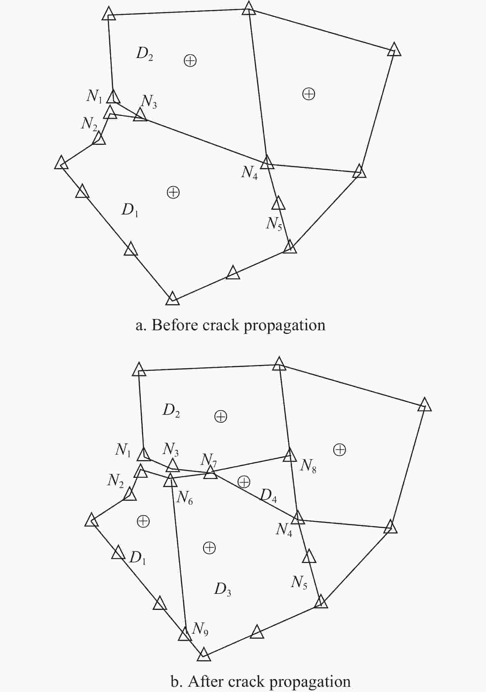
Figure 6. Remeshing strategy of NFCP of stage I with Δθc≥θc
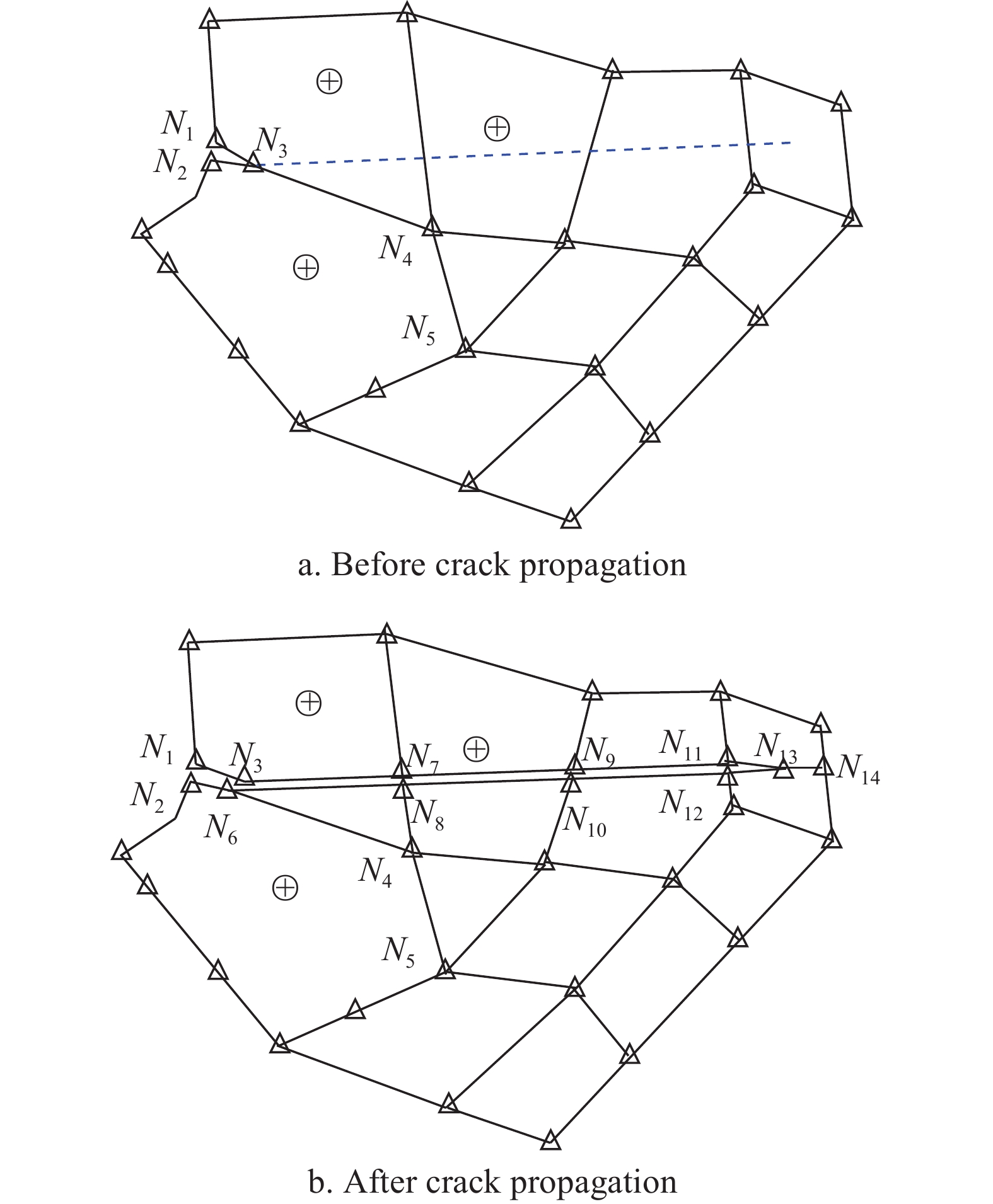
At stage II, the remeshing and optimization strategy[43] is appropriate for modeling the fatigue crack propagations and adopted in this study. As for the last stage, nature fatigue cracks under one cyclic loading may propagate through several subdomains, see the dashed lines in Fig. 7a and Fig. 8a. To properly handle this issue, two cases are considered here and the remeshing strategies in Fig. 7b and Fig. 8b are employed to generate the discretized models for simulations with SBFEM.
Up to now, the computational strategy using the SBFEM to numerically simulate the 2D NFCP phenomenon has been introduced completely, and an in-house package may be developed by using C++, MATLAB or others to perform the simulations. The whole process is summarized as a flow chart presented in Fig. 9.
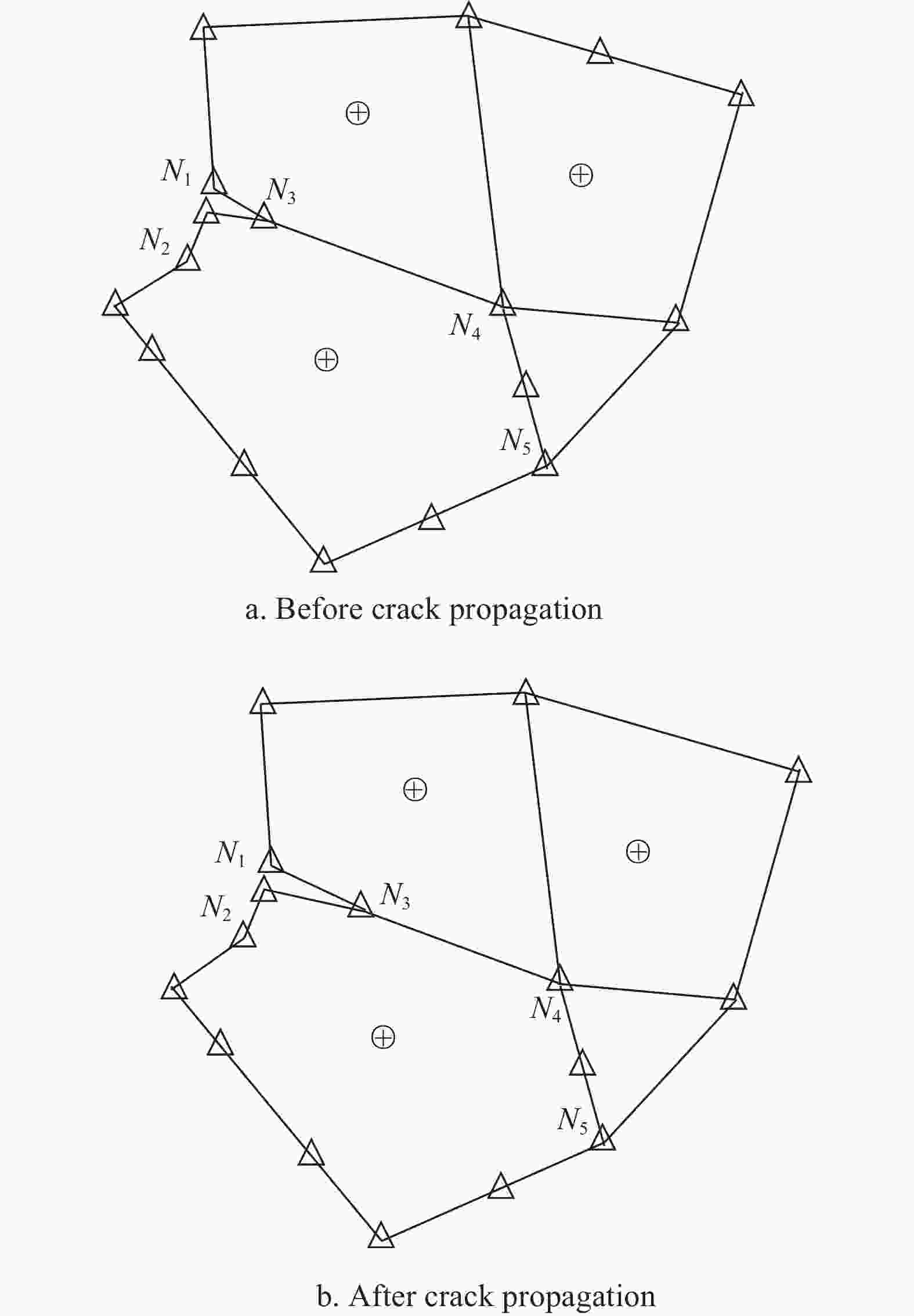
Figure 5. Illustration of NFCP of stage I with Δθc≤θc
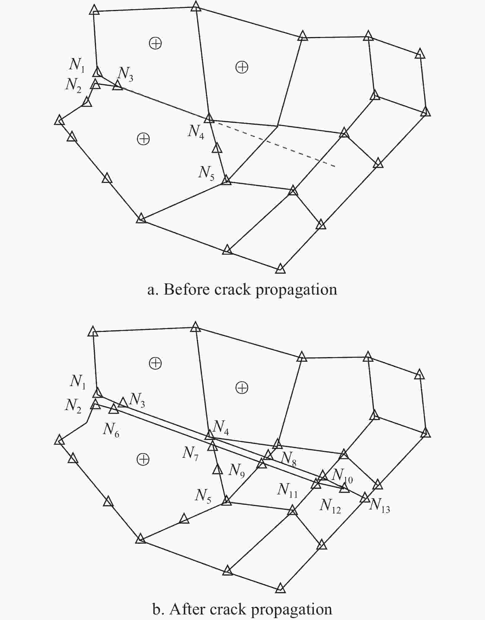
Figure 7. Remeshing strategy of NFCP of stage III (case 1)
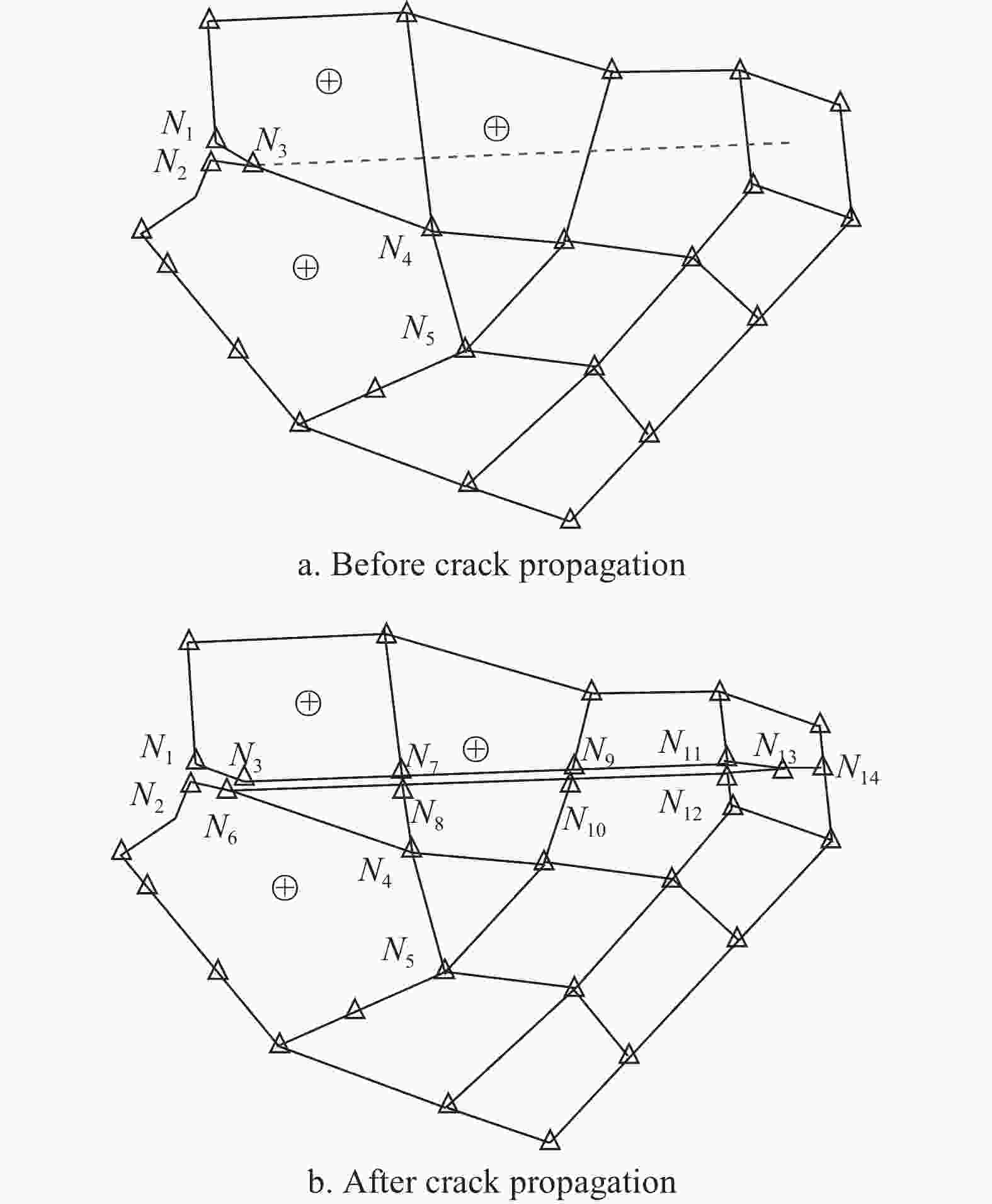
Figure 8. Remeshing strategy of NFCP of stage III (case 2)
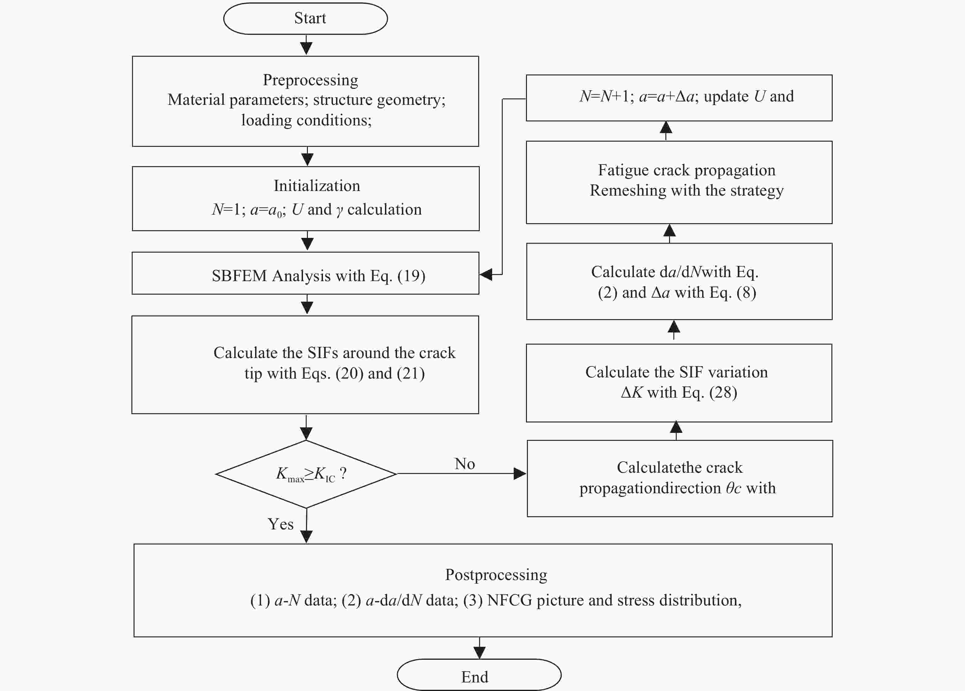
Figure 9. Flow chart of simulating NFCGs with SBFEM
-
In this work, we established a computational methodology framed within SBFEM to simulate the natural fatigue crack growth and to predict the fatigue lifetime of thin-walled plates considering the influence of the loading conditions and the specimen characteristics simultaneously. To be noted, the effects of loading conditions, specimen thickness and material properties could be studied with our elaborated methodology to serve as a beneficial tool for quantitatively studying the natural fatigue crack propagations and designing practical specimens.
-
This work was funded by the Young Scientific Innovation Team of Science and Technology of Sichuan (2017TD0017).
Simulation of Natural Fatigue Crack Propagation in Thin-walled Structures Using SBFEM
-
摘要: 自然疲劳裂纹扩展(NFCG)对关键部件的整体寿命有着重要影响,且机理复杂,几十年来被广泛研究。该文首先引用了基于疲劳裂纹扩展现象观察的NFCG模型,并利用比例边界有限元(SBFEM)方法模拟NFCG现象,提出了一种计算策略,预测不同厚度试样在不同循环加载条件下的疲劳寿命。本工作所建立的仿真策略可深入探讨加载条件、试件厚度和材料特性对自然疲劳裂纹扩展过程的影响,为实际试件设计、材料选择和涡流检测提供了有益的工具。Abstract: Natural fatigue crack growth (NFCG) has been investigated extensively for decades due to its significant influence on the overall life of key components and the complex mechanism involved. In this study, a NFCG model based on the phenomenological observations of fatigue crack growth is first invoked, and a computational strategy is developed in the scaled boundary finite element method (SBFEM) context to simulate the NFCG phenomenon and to predict the fatigue life of specimen with different thicknesses under various cyclic loading conditions. The effects ascribed to the loading conditions, specimen thickness and material properties on the NFCG can be investigated in detail with the our elaborated strategy, which provides a helpful tool for practical specimen design, material selection and eddy current testing.
-
[1] YIN H, WEN G, LIU Z, et al. Crashworthiness optimization design for foam-filled multi-cell thin-walled structures[J]. Thin-Walled Structures, 2014, 75: 8-17. doi: 10.1016/j.tws.2013.10.022 [2] OBERST S, TUTTLE S L, GRIFFIN D, et al. Experimental validation of tape springs to be used as thin-walled space structures[J]. Journal of Sound and Vibration, 2018, 419: 558-570. doi: 10.1016/j.jsv.2018.01.014 [3] ZHONG H, LIU Z, QIN H, et al. Static analysis of thin-walled space frame structures with arbitrary closed cross-sections using transfer matrix method[J]. Thin-Walled Structures, 2018, 123: 255-269. doi: 10.1016/j.tws.2017.11.018 [4] YIN D, LIU H, CHEN Y, et al. Effect of grain size on fatigue-crack growth in 2524 aluminium alloy[J]. International Journal of Fatigue, 2016, 84: 9-16. doi: 10.1016/j.ijfatigue.2015.11.011 [5] XU W, YANG X, ZHONG B, et al. Failure criterion of titanium alloy irregular sheet specimens for vribration-based bending fatigue testing[J]. Engineering Fracture Mechanic, 2018, 195: 44-56. doi: 10.1016/j.engfracmech.2018.03.031 [6] PATANKAR R, RAY A, LAKHTAKIS A. A state-space model of fatigue crack growth[J]. International Journal of Fracture, 1998, 90(3): 235-49. doi: 10.1023/A:1007491916925 [7] MCMASTER F J, SMITH D J. Predictions of fatigue crack growth in aluminium alloy 2024-T351 using constraint factors[J]. International Journal of Fatigue, 2001, 23(1): 93-101. doi: 10.1016/S0142-1123(01)00134-7 [8] LIU J T, DU P A, ZHANG Z Y. A general model of fatigue crack growth under variable amplitude loading[J]. Science China Technological Sciences, 2012, 55(8): 673-683. doi: 10.1007/s11431-011-4656-x [9] MOËS N, DOLBOW J, BELYTSCHKO T. A finite element method for crack growth without remeshing[J]. International Journal for Numerical Methods in Engineering, 1999, 46(1): 131-20. doi: 10.1002/(SICI)1097-0207(19990620)45:5<601::AID-NME598>3.0.CO;2-S [10] WOLF J P, SONG C. The Scaled boundary finite-element method-a primer: Derivations[J]. Computers and Structures, 2000, 78(1): 191-210. doi: 10.1016/S0045-7949(00)00099-7 [11] SONG C, WOLF J P. The Scaled boundary finite-element method-a primer: Solution procedures[J]. Computers and Structures, 2000, 78: 211-225. doi: 10.1016/S0045-7949(00)00100-0 [12] GATO C. Meshfree analysis of dynamic fracture in thin-walled structures[J]. Thin-Walled Structures, 2010, 48: 215-222. doi: 10.1016/j.tws.2009.10.011 [13] SONG C, OOI E T, NATARAJAN S. A review of the scaled boundary finite element method for two-dimensional linear elastic fracture mechanics[J]. Engineering Fracture Mechanics, 2018, 187: 45-73. doi: 10.1016/j.engfracmech.2017.10.016 [14] XING C, WANG Y, WAISMAN H. Fracture analysis of cracked thin-walled structures using a high-order XFEM and Irwin’s integral[J]. Computers and Structures, 2019, 212: 1-19. [15] LI H, LI J, YUAN H. A review of the extended finite element method on macrocrack and microcrack growth simulations[J]. Theoretical and Applied Fracture Mechanic, 2018, 97: 236-249. doi: 10.1016/j.tafmec.2018.08.008 [16] MIEHE C, SCHÄNZEL L M, ULMER H. Phase field modeling of fracture in multi-physics problems. Part I. Balance of crack surface and failure criteria for brittle crack propagation in thermo-elastic solids[J]. Computer Methods in Applied Mechanics and Engineering, 2015, 294: 449-485. doi: 10.1016/j.cma.2014.11.016 [17] PATIL R U, MISHRA B K, SINGH I V, et al. A new multiscale phase field method to simulate failure in composites[J]. Advances in Engineering Software, 2018, 126: 9-33. doi: 10.1016/j.advengsoft.2018.08.010 [18] WOLF J P, SONG C. The Scaled boundary finite-element method – a fundamental solution-less boundary-element method[J]. Computer Methods in Applied Mechanics and Engineering, 2001, 190: 5551-5568. doi: 10.1016/S0045-7825(01)00183-9 [19] ZHANG Z, DISSANAYAKE D, SAPUTRA A, et al. Three-dimensional damage analysis by the scaled boundary finite element method[J]. Computers and Structure, 2018, 206: 1-17. [20] CHOWDHURY M S, SONG C, GAO W, et al. Reliability analysis of homogeneous and bimaterial cracked structures by the scaled boundary finite element method and hybrid random-interval model[J]. Structural Safety, 2019, 59: 53-66. [21] WOLF J P, SONG C. Consistent infinitesimal finite-element cell method: Three dimensional vector wave equation[J]. International Journal for Numerical Methods in Engineering, 1996, 39: 2189-2208. doi: 10.1002/(SICI)1097-0207(19960715)39:13<2189::AID-NME950>3.0.CO;2-P [22] DEEKS A J , WOLF J P. A virtual work derivation of the scaled boundary finite-element method for elastostatics[J]. Computational Mechanics, 2002, 28(6): 489-504. doi: 10.1007/s00466-002-0314-2 [23] OOI E T, YANG Z J. Modelling multiple cohesive crack propagation using a finite element-scaled boundary finite element coupled method[J]. Engineering Analysis with Boundary Elements, 2009, 33: 915-929. doi: 10.1016/j.enganabound.2009.01.006 [24] SONG C, TINLOI F, GAO W. Transient dynamic analysis of interface cracks in anisotropic bimaterials by the scaled boundary finite-element method[J]. International Journal of Solids and Structures, 2010, 47(7): 978-989. doi: 10.1016/j.ijsolstr.2009.12.015 [25] HELL S, BECKER W. The scaled boundary finite element method for the analysis of 3D crack interaction[J]. Journal of Computational Science, 2015, 9: 76-81. doi: 10.1016/j.jocs.2015.04.007 [26] ZHONG H, LI H, OOI E T, et al. Hydraulic fracture at the dam-foundation interface using the scaled boundary finite element method coupled with the cohesive crack model[J]. Engineering Analysis with Boundary Elements, 2018, 88: 41-53. doi: 10.1016/j.enganabound.2017.11.009 [27] BIRK C, SONG C. A continued-fraction approach for transient diffusion in unbound medium[J]. Computer Methods in Applied Mechanics and Engineering, 2009, 198(33): 2576-2590. doi: 10.1016/j.cma.2009.03.002 [28] WANG Y, LIN G, HU Z. Novel nonreflecting boundary condition for an infinite reservoir based on the scaled boundary finite element method[J]. Journal of Enginneering Mechanics, 2015, 141: 04014150. [29] LIU J, ZHANG P, LIN G, et al. Solutions for the magneto-electro-elastic plate using the scaled boundary finite element method[J]. Engineering Analysis with Boundary Elements, 2016, 68: 103-114. doi: 10.1016/j.enganabound.2016.04.005 [30] LI J, SHI Z, LIU L. A unified scaled boundary finite element method for transient two-dimensional vibro-acoustic analysis of plate-like structures[J]. Computers and Structures, 2018, 202: 105-128. [31] NATARAJAN S, WANG J C, SONG C, et al. Isogeometric analysis enhanced by the scaled boundary finite element method[J]. Computer Methods in Applied Mechanics and Engineering, 2015, 283: 733-762. doi: 10.1016/j.cma.2014.09.003 [32] CHEN X, LUO T, OOI E T, et al. A quadtree-polygon-based boundary finite element method for crack propagation modeling in functionally graded materials[J]. Theoretical and Applied Fracture Mechanics, 2018, 94: 120-133. doi: 10.1016/j.tafmec.2018.01.008 [33] SONG C. The scaled boundary finite element method: Introduction to theory and implementation[M]. Hoboken: John Wiley & Sons Ltd, 2018. [34] GAYLON S E, ARUNACHALAM S R, GREER J, et al. Three dimensional crack growth prediction[C]//Symposium of the International Committee on Aeronautical Fatigue (ICAF 2009). Rotterdam, Netherlands: [s.n], 2009: 1035-1068. [35] XU F M, ZHU S J, ZHAO J, et al. Effect of stress ratio on fatigue crack propagation in a functionally graded metal matrix composite[J]. Composites Science and Technology, 2004, 64: 1795-1803. doi: 10.1016/j.compscitech.2004.01.009 [36] JOYCE M R, STARINK M J, SINCLAIR I. Assessment of mixed mode loading on macroscopic fatigue crack paths in thick section Al-Cu-Li alloy plate[J]. Materials and Design, 2016, 93: 379-387. doi: 10.1016/j.matdes.2015.12.116 [37] PARIS P, ERDOGAN F. A critical analysis of crack growth laws[J]. Journal of Basic Engineering, 1963, 85(4): 529-534. [38] PATANKAR R, QU R. Validation of the state-space model of fatigue crack growth in ductile alloys under variable-amplitude load via comparison of the crack-opening stress data[J]. International Journal of Fracture, 2005, 131(4): 337-349. doi: 10.1007/s10704-004-4729-y [39] LIU J T, DU P A, HUANG M J, et al. New model of propagation rates of long crack due to structure fatigue[J]. Applied Mathematics and Mechanics, 2009, 30: 575-584. doi: 10.1007/s10483-009-0504-y [40] HUANG X P, TORGEIR M, CUI W C. An engineering model of fatigue crack growth under variable amplitude loading[J]. International Journal of Fatigue, 2008, 30(1): 2-10. doi: 10.1016/j.ijfatigue.2007.03.004 [41] NEWMAN J C, RUSCHAU J J. The stress-level effect on fatigue-crack growth under constant-amplitude loading[J]. International Journal of Fatigue, 2007, 29(9): 1608-1615. doi: 10.1016/j.ijfatigue.2006.11.003 [42] YANG Z. Fully automatic modelling of mixed-model crack propagation using scaled boundary finite element method[J]. Engineering Fracture Mechanics, 2006, 73(12): 1711-1731. doi: 10.1016/j.engfracmech.2006.02.004 [43] DAI S, AUGARDE C, DU C, et al. A fully automatic polygon scaled boundary finite element method for modelling crack propagation[J]. Engineering Fracture Mechanics, 2015, 133: 163-178. -

 点击查看大图
图(9)
计量
- 文章访问数: 4544
- HTML全文浏览量: 1464
- PDF下载量: 34
- 被引次数: 0