ISSN
ISSN 


-
With the development of the Internet of things and intelligent technology, automatic access detection has attracted more and more attention in real life due to its commercial and social values[1], such as security places[2], business offices[3], and school[4-5]. Currently, the existing access detection technology consists of video surveillance, infrared, ultrasonic, WIFI (wireless fidelity), RFID (radio frequency identification), and other wireless sensors methods[6]. The detection technology based on video monitoring is limited by observation angle and external environment[7]. This method will not work if the target is covered by other objects or the information is insufficient. Although the infrared technology has high accuracy, it is expensive to set up and short-range[8]. Similarly, the ultrasonic technology is also high-cost and strongly affected by unnecessary objects such as a puppy[9]. Wi-Fi is easy to expand and has a wide application field. However, it would bring about high energy consumption[10] and is affected by obstacles and the multipath effect. The RFID technology can be applied in the access control system because of low cost and low power consumption[11], which uses received signal strength indicator (RSSI) for location[12]. UHF RFID signals are easily reflected by objects to generate multipath signals, and they are strongly attenuated during propagation. Therefore, UHF signals are not a reliable choice in complex indoor environments. In addition, low frequency (LF) signal in the 125 kHz is less influenced by multipath and has the characteristics of high reliability and low positioning latency, and LF RFID has been used on a large scale in many scenarios[13-16].
In recent years, scholars have studied many detection algorithms and localization algorithms based on LF RFID in various applications. Ref. [17] designed an LF RFID-based attendance management system. The system manages student attendance records and tracks student absences. Ref. [18] proposed an access detection algorithm based on LF RFID in the vehicle keyless entry system. The algorithm detects the location of the key based on the RSSI. Ref. [19] studied a localization and tracking algorithm based on RFID. Then, the estimate position of the RFID reader is obtained by compensating for the artifacts of multipath propagation and non-isotropic antenna pattern. Ref. [20] designed an indoor location system based on RFID. The effectiveness of this system is verified in static positioning and dynamic positioning scenarios. Ref. [21] proposed a new Mobile RFID (M-RFID)-based Localization approach for indoor human tracking. RFID readers are equipped on the moving objects and RFID tags are fixed deployed in the monitoring area[21]. Ref. [22] presented the RFID-based indoor inventory localization method in multi-stacking racks for warehousing. It was noted that there was no significant location difference between the estimate location information and the actual location of the item in the rack. Ref. [23] proposed the localization method based on maximum likelihood estimation with the help of RFID tags and RFID receiving antennas. The target position is estimated by the maximum likelihood algorithm and real-time localization is implemented by using an extended Kalman filter. Ref. [24] demonstrates that it is difficult to avoid the RSSI ranging error due to environmental disturbances, especially in metallic environments. These RSSI-based localization methods suffer from poor stability and low accuracy because of the ranging error. In the real detection environment, metal doors are one of the most common environmental interferences for RSSI ranging. Other factors include: electronic equipment, metal objects, and uneven magnetic field distribution, etc[25-26]. The angles of the metal doors often change dynamically as people enter and exit, and this dynamic metal environment usually results in inaccurate RSSI and thus indirectly causes positioning errors and detection errors.
Positioning is the basis of access detection technology. Furthermore, the positioning accuracy in the entry/exit is the key to the detection accuracy for access detection systems. The real-time detection systems in entry/exit require high localization accuracy in the order of a few centimeters[27]. In order to improve the positioning accuracy and algorithm stability near the entrance/exit, an access detection (entry and exit) method based on RFID is proposed in this paper, including a corresponding positioning algorithm using improved maximum likelihood estimation. The positioning method consists of the training stage and positioning stage. In the training stage, at first, the RSSIs ranging from the environment-aware tag to the main base station (BS) and from the reference tag to all BSs are collected in a dynamic metal environment. Secondly, the ranging dataset is fitted by the least square algorithm to obtain the fitting parameters. Finally, the correction fingerprint database is built. In the positioning stage, the correction fingerprint database is used to correct the RSSI ranging error due to the dynamic metal environment. Then, the maximum likelihood algorithm is used for positioning. The optimized maximum likelihood algorithm can eliminate the impact of metal interference, thereby improving the positioning accuracy and detection accuracy.
-
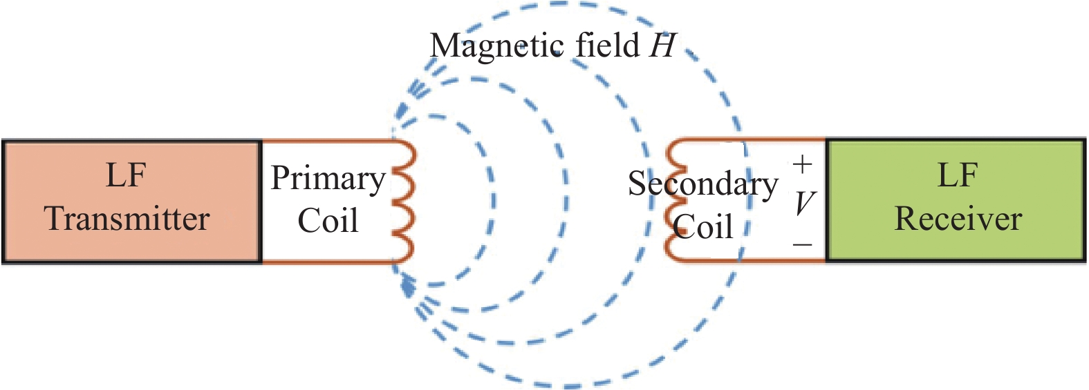
The LF RFID technology depends on near-field magneto inductive communication (NFMIC) in Fig. 1, which is achieved by magnetic coupling between the receiver and the transmitter[28]. By inductive coupling, it is possible to convert the electromagnetic field energy into an induced electric potential to generate a voltage on the tag. When the voltage is greater than a certain level, the tag is activated (wake-up) and the tag can obtain energy from the radiated near field of the transmitter. When transmitting data between the tag and the reader, the low-frequency tag needs to be located in the near-field region radiated by the reader antenna. The magnetic field strength decays rapidly with increasing distance between transmitter and receiver[29].
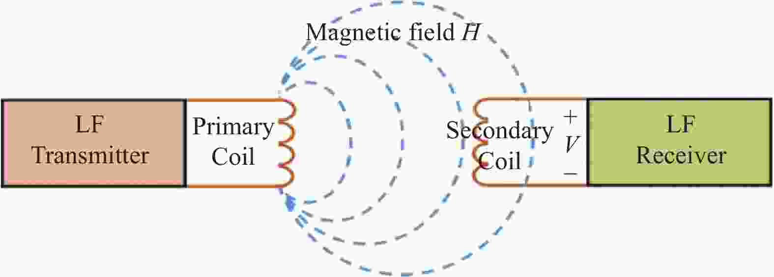
Figure 1. Near-field magneto inductive coupling
-
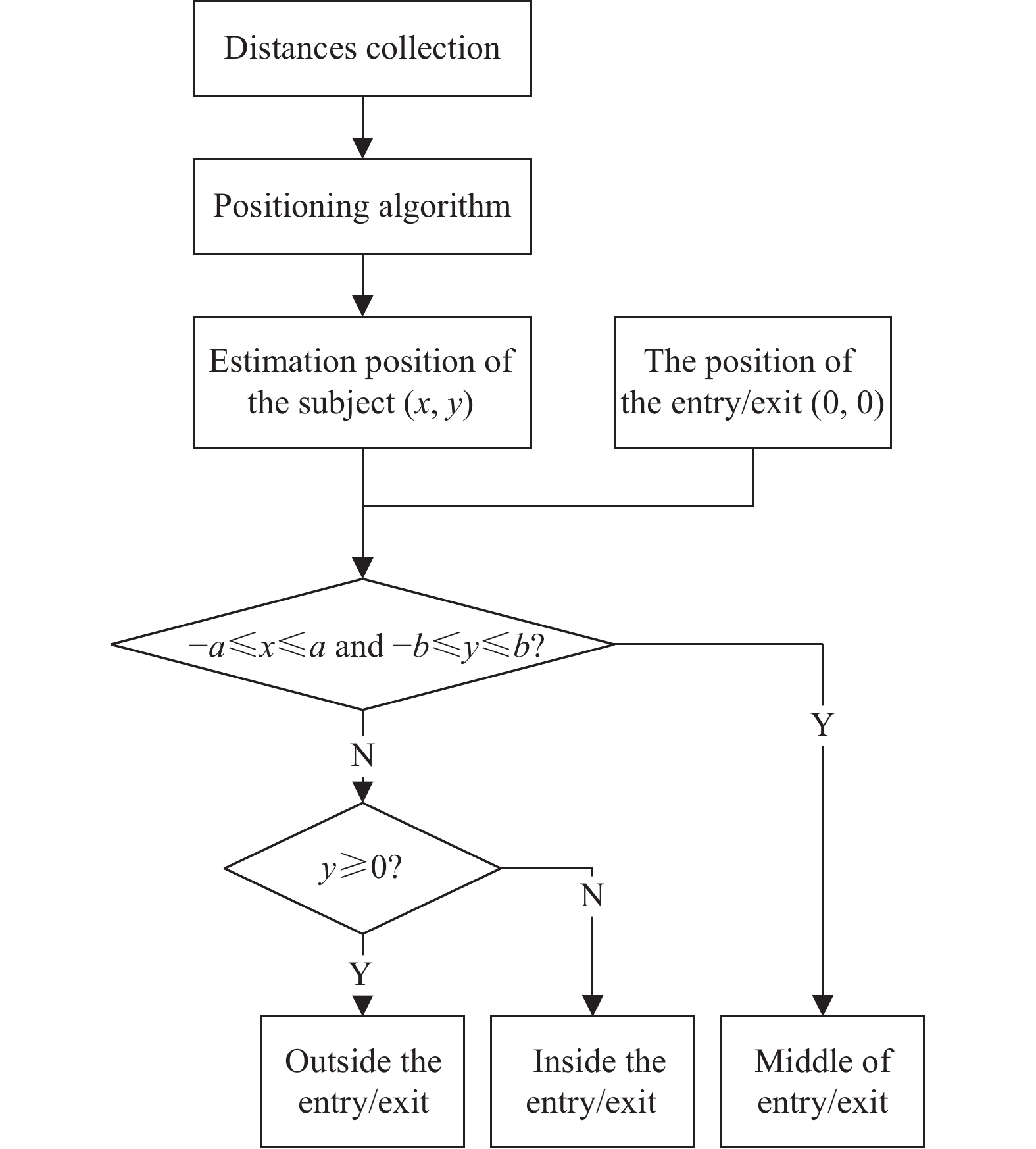
Firstly, to clarify the structure of the access detection method, there is a flowchart of this detection method in Fig. 2 .
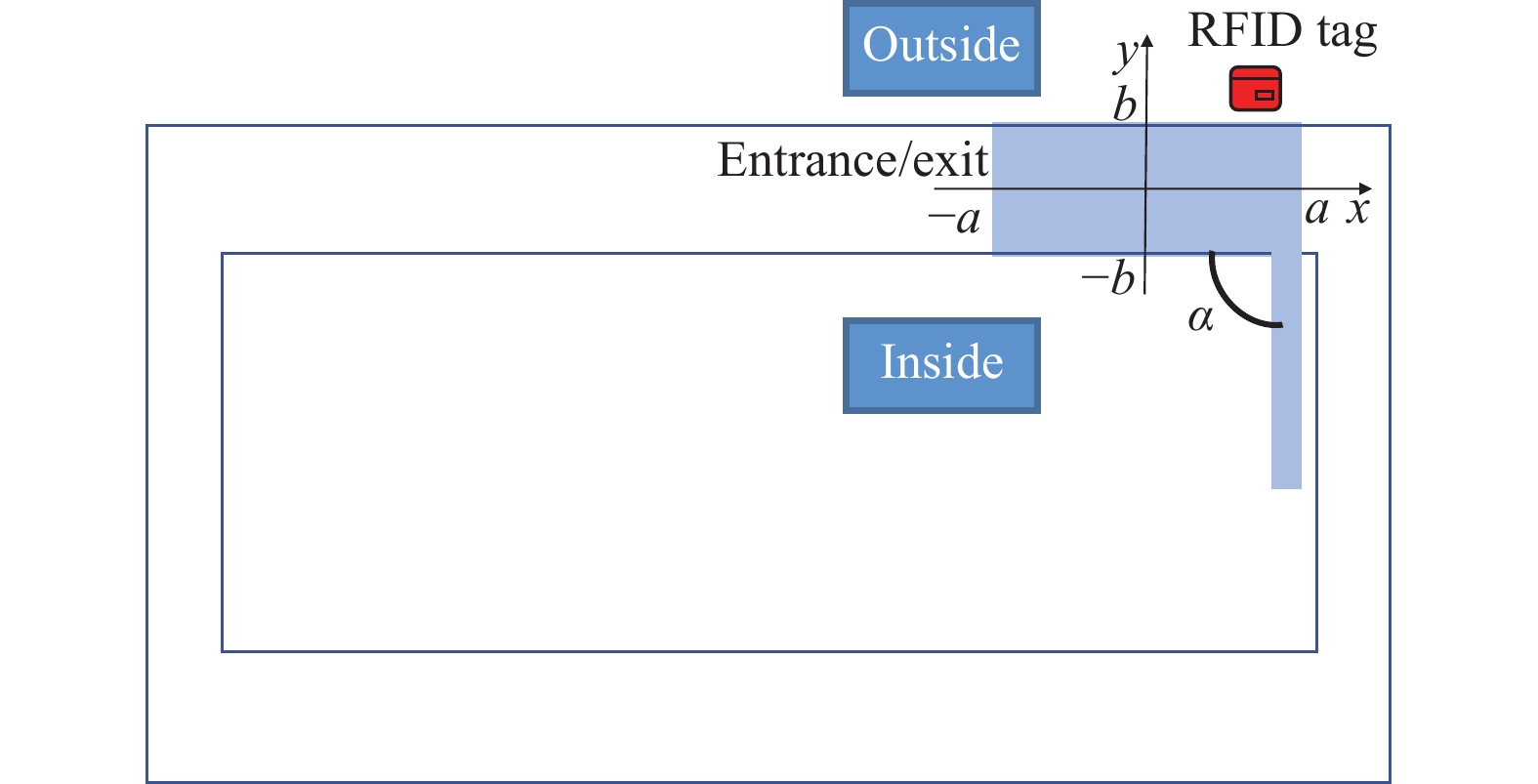
Then, the top view diagram of entrance/exit is shown in Fig. 3, where a is half of the length of the entrance/exit, b is half of the width of the entrance/exit, and
$\alpha $ is the opening and closing angle of the metal door.At the beginning of the detection algorithm, the tag needs to be confirmed to be activated. The positioning algorithm will only work when the tag is active. Then, the estimated position of the subject is compared with the position of the entrance/exit to confirm the entry and exit status of the subject. When − a < x < a and − b < y < b, it is determined that the tag is in the middle of the entry/exit, and when y ≥ 0, the tag is inside the entry/exit, otherwise, the tag is outside the entry/exit.

Figure 2. Flowchart of the detection algorithm

Figure 3. Scene diagram of exit/entrance
Moreover, since LF RFID is based on RSSI for position estimation, then the RSSI ranging model needs to be found. Some RSSI with distance was measured at predefined locations in the environment. Then, a mathematical relationship between distance and RSSI was obtained by data fitting based on RSSI and distance, which converted the RSSI to the distance between the tag and BSs. Finally, the positioning algorithm was described, which is the core of the entry/exit detection algorithm.
-
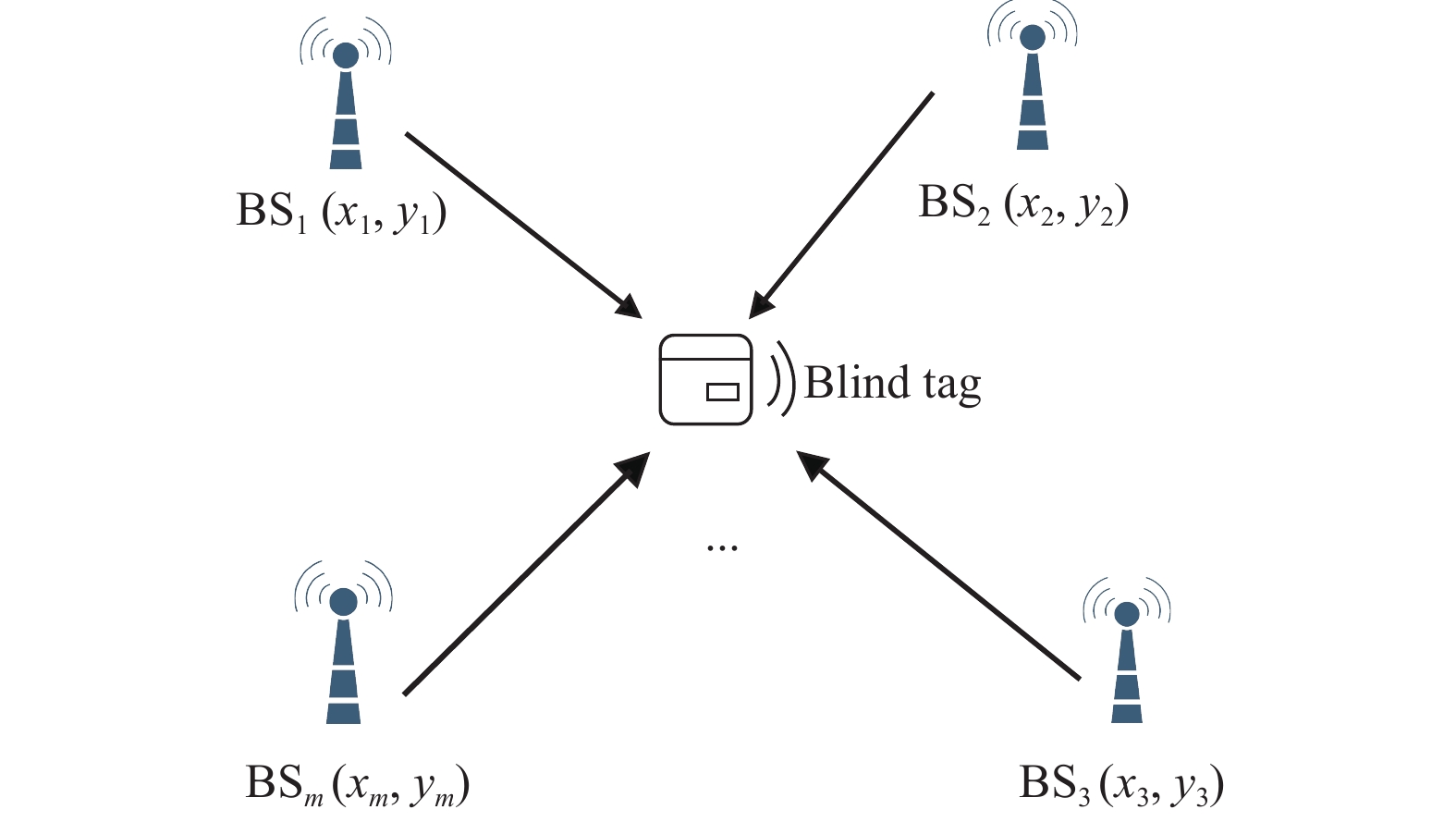
The basic idea of the maximum likelihood (ML) positioning method is based on the RSSI ranging[23], in which there are some base stations
${\rm{B}}{{\rm{S}}_i}(i = 1,2,\cdots,m)$ as depicted in Fig. 4. The real location of each BS is$ ({x_i},{y_i}) $ and the location of the blind tag is$ (x,y) $ . A blind tag indicates a tag whose position is not clear and needs to be located. The distances between the blind tag and BSs are${d_1},{d_2}, \cdots {d_m}$ .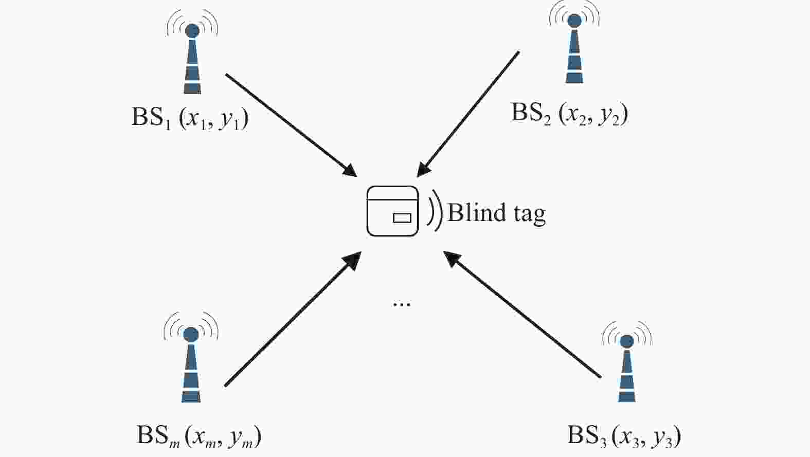
Figure 4. Distribution of tag and base stations
$$ \left\{ \begin{gathered} {\left( {{x_1} - x} \right)^2} + {\left( {{y_1} - y} \right)^2} = d_1^2 \\ {\left( {{x_2} - x} \right)^2} + {\left( {{y_2} - y} \right)^2} = d_2^2 \\ \qquad\quad\qquad \vdots \\ {\left( {{x_m} - x} \right)^2} + {\left( {{y_m} - y} \right)^2} = d_m^2 \\ \end{gathered} \right.\; $$ (1) Generally, equation (1) is converted to
${{{\boldsymbol{AX}}}} = {{{\boldsymbol{B}}}}$ , where the matrix${{{\boldsymbol{A}}}}$ ,${{{\boldsymbol{B}}}}$ and${{{\boldsymbol{X}}}}$ are shown below.$$ {{{\boldsymbol{A}}}} = 2 \times \left( {\begin{array}{*{20}{c}} {({x_1} - {x_m}),({y_1} - {y_m})} \\ {({x_2} - {x_m}),({y_2} - {y_m})} \\ \vdots \\ {({x_{m - 1}} - {x_m}),({y_{m - 1}} - {y_m})} \end{array}} \right) $$ (2) $$ {{{\boldsymbol{B}}}} = \left( {\begin{array}{*{20}{c}} {x_1^2 - x_m^2 + y_1^2 - y_m^2 + d_m^2 - d_1^2} \\ {x_2^2 - x_m^2 + y_2^2 - y_m^2 + d_m^2 - d_2^2} \\ \vdots \\ {x_{m - 1}^2 - x_m^2 + y_{m - 1}^2 - y_m^2 + d_m^2 - d_{m - 1}^2} \end{array}} \right) $$ (3) $$ {{{\boldsymbol{X}}}} = {(x,y)^{\rm{T}}}\; $$ (4) By solving above equations with the least square method, the mean square error can be minimized. If the equation has a solution, then the position of the blind tag is
${{{\boldsymbol{X}}}}{{ = (}}{{{\boldsymbol{A}}}}{{{{\boldsymbol{A}}}}^{\rm{T}}}{{{)}}^{{{ - 1}}}}{{{\boldsymbol{AB}}}}$ .The principle of the traditional ML algorithm is simple. However, the algorithm is instable and is susceptible to metal interference because of
$\alpha $ . The reason is that the metal door with different$\alpha $ will affect the distribution of the electromagnetic field, which will cause the inaccurate RSSI received by the blind tag. The positioning effects will be affected by inaccurate RSSI. Therefore, the traditional ML algorithm has a problem with low accuracy and poor stability in the metal environment. -
To solve the problem of the traditional ML method, this paper designs an optimized ML algorithm, which contains the training stage and the positioning stage. The process of the algorithm is shown in Fig. 5.
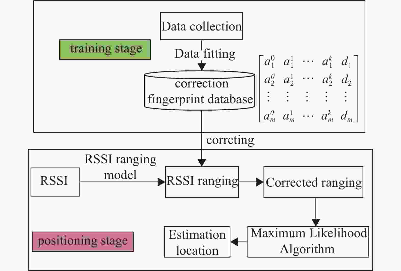
Figure 5. Process of the accurate positioning algorithm
Compared with the traditional ML, this improved algorithm takes into account the influence of metal interference, which uses the correction fingerprint database to correct the ranging error. Accurate RSSI enhances the positioning accuracy, thus improving detection accuracy. There are three main steps in the training stage, including data collection, data fitting, and calculation of the correction fingerprint database.
1) The data collection
The effective detection area is divided into p raster areas, and the center of each raster area is used as a reference point. For every reference point, a reference tag is placed on a reference point to collect distance.
The metal door opens from the fully closed according to a certain angle interval, which is divided into n angles. The distance measurement vector from the environment-aware tag to the main BS (any one of the BSs) is as follows.
$$ {{{{\boldsymbol{d}}}}_{{{{\rm{ev}}}}}}{{ = }}{\left[ {\begin{array}{*{20}{c}} {d_{{\rm{ev}}}^1}&{d_{{\rm{ev}}}^2}& \cdots &{d_{{\rm{ev}}}^n} \end{array}} \right]^{\rm{T}}}\; $$ (5) where
$ d_{{\rm{ev}}}^j,(j = 1,2,\cdots,n) $ is the distance at the jth angle.The distance measurement matrix from the reference tag
$i$ to all BSs is:$$ {{{\boldsymbol{d}}}}_{{{{\rm{ref}}}}}^{} = \left[ {\begin{array}{*{20}{c}} {d_{i,1}^1}&{d_{i,1}^2}& \cdots &{d_{i,1}^n} \\ {d_{i,2}^1}&{d_{i,2}^2}& \cdots &{d_{i,2}^n} \\ \vdots & \vdots & \vdots & \vdots \\ {d_{i,m}^1}&{d_{i,m}^2}& \cdots &{d_{i,m}^n} \end{array}} \right] $$ (6) where
$d_{i,m}^j$ is the distance from the reference tag$i$ to the mth BS at the jth angle.2) The fitting of curves
For a reference point, the dataset is composed of the distances from the environment-aware tag and from the reference tag under different angles, which looks like
$\left\{ {\left. {\left( {d_{{\rm{ev}}}^1,d_{i,m}^1} \right),\left( {d_{{\rm{ev}}}^2,d_{i,m}^2} \right),\cdots,\left( {d_{{\rm{ev}}}^n,d_{i,m}^n} \right)} \right\}} \right.(m > 3)$ . Then, the fitted curves for all BSs can be obtained by fitting this dataset using the least-squares method, which can minimize the training error. The mathematical expressions of the fitting curves are as follows.$$ \begin{array}{*{20}{c}} {{f_{i,1}}({d_{{\rm{ev}}}}) = a_{i,1}^0 + a_{i,1}^1d_{{\rm{ev}}}^1 + \cdots + a_{i,1}^k{d_{{\rm{ev}}}}^k = \displaystyle\sum\limits_{k = 0}^n {a_{i,1}^k{d_{{\rm{ev}}}}^k} } \\ {{f_{i,2}}({d_{{\rm{ev}}}}) = a_{i,2}^0 + a_{i,2}^1d_{{\rm{ev}}}^1 + \cdots + a_{i,2}^k{d_{{\rm{ev}}}}^k = \displaystyle\sum\limits_{k = 0}^n {a_{i,2}^k{d_{{\rm{ev}}}}^k} } \\ {\cdots} \\ {{f_{i,m}}({d_{{\rm{ev}}}}) = a_{i,m}^0 + a_{i,m}^1d_{{\rm{ev}}}^1 + \cdots + a_{i,m}^k{d_{{\rm{ev}}}}^k = \displaystyle\sum\limits_{k = 0}^n {a_{i,m}^k{d_{{\rm{ev}}}}^k} } \end{array} $$ (7) where
$a_{i,m}^k(i = 1,2,\cdots,p)$ is the kth term coefficient of the fitting curve of the reference tag about the mth BS.3) The calculation of the correction fingerprint database.
These parameters of the above fitting curves are combined into the fingerprint of the reference point.
$$ {{{\bf{F}}}}{{{{\bf{P}}}}_{{i}}}{\text{ = }}\left[ {\begin{array}{*{20}{c}} {a_{i,1}^0}&{a_{i,1}^1}& \cdots &{a_{i,1}^k} \\ {a_{i,2}^0}&{a_{i,2}^1}& \cdots &{a_{i,2}^k} \\ \vdots & \vdots & \vdots & \vdots \\ {a_{i,m}^0}&{a_{i,m}^1}& \cdots &{a_{i,m}^k} \end{array}} \right] $$ (8) The real distance vector from the reference point to all BSs is below:
$$ {{{{\boldsymbol{D}}}}_{{i}}} = {\left[ {\begin{array}{*{20}{c}} {{d_{i,1}}}&{{d_{i,2}}}& \cdots &{{d_{i,m}}} \end{array}} \right]^{\rm{T}}} $$ (9) where
${d_{i,m}}$ is the real distance between the reference point$i$ and mth BS.So far, the correction fingerprint of a reference point has been finished, and the expression is as follows:
$$ {{{\bf{CFD}}}}{{{{\bf{B}}}}_{{i}}} = \left[ {{{{\bf{F}}}}{{{{\bf{P}}}}_{{i}}}{{,}}{{{{\bf{D}}}}_{{i}}}} \right] $$ (10) and then repeating 1), the correction fingerprint is established for each reference point, and thus the correction fingerprint database is obtained.
In the positioning stage, there are two main steps, including error correction and position estimation. Firstly, according to the distance
$ {d_{{\rm{en}}}} $ from the environment-aware tag to the main BS and the fingerprint${\bf{F}}{{\bf{P}}_i}$ of the reference point, the distance measurement from the reference tag to BSs is:$$ {{{{\boldsymbol{D}}}}_{{{{\rm{ref}}\_{\rm{m}}}}}} = {\left[ {\begin{array}{*{20}{c}} {{f_{i,1}}({d_{{\rm{en}}}})}&{{f_{i,2}}({d_{{\rm{en}}}})}&{\cdots}&{{f_{i,m}}({d_{{\rm{en}}}})} \end{array}} \right]^{\rm{T}}}\; $$ (11) Comparing the distance measurement with the real distance
$ {{{{\boldsymbol{D}}}}_{{i}}} $ , the ranging error$ {{{{\boldsymbol{d}}}}_{{{\Delta m}}}} $ of the reference tag can be calculated as:$$ {{{{\boldsymbol{d}}}}_{{{\Delta m}}}}{{ = }}{{{{\boldsymbol{D}}}}_{{i}}}{{ - }}{{{{\boldsymbol{D}}}}_{{{{\rm{ref}}\_{\rm{m}}}}}}\; $$ (12) According to the consistency of local field strength measurement error, it can be considered that the ranging error of the blind tag is the same as that of the reference tag. Then the measurement distance vector of the blind tag to BSs after ranging correction is below:
$$ {{{{\boldsymbol{D}}}}_{{c}}}{\text{ = }}{\left[ {\begin{array}{*{20}{c}} {{d_1}}&{{d_2}}&{\cdots}&{{d_m}} \end{array}} \right]^{\rm{T}}}{{ = }}{{{{\boldsymbol{D}}}}_{{m}}}{{ + }}{{{{\boldsymbol{d}}}}_{{{\Delta m}}}} $$ (13) where
$ {{{{\boldsymbol{D}}}}_{{m}}} $ is the distance measurement before ranging correction, and${{{{\boldsymbol{D}}}}_{{c}}}$ is the distance measurement after ranging correction.Secondly, based on the corrected distance measurement, the position of the blind tag can be estimated by using equation (2) to equation (4).
-
To verify the effectiveness of the access detection method proposed in this paper, the positioning method was tested in the detection area. Then, subjects carried the RFID tag and passed through the detection area at any speed for determining the access status of subjects.
-
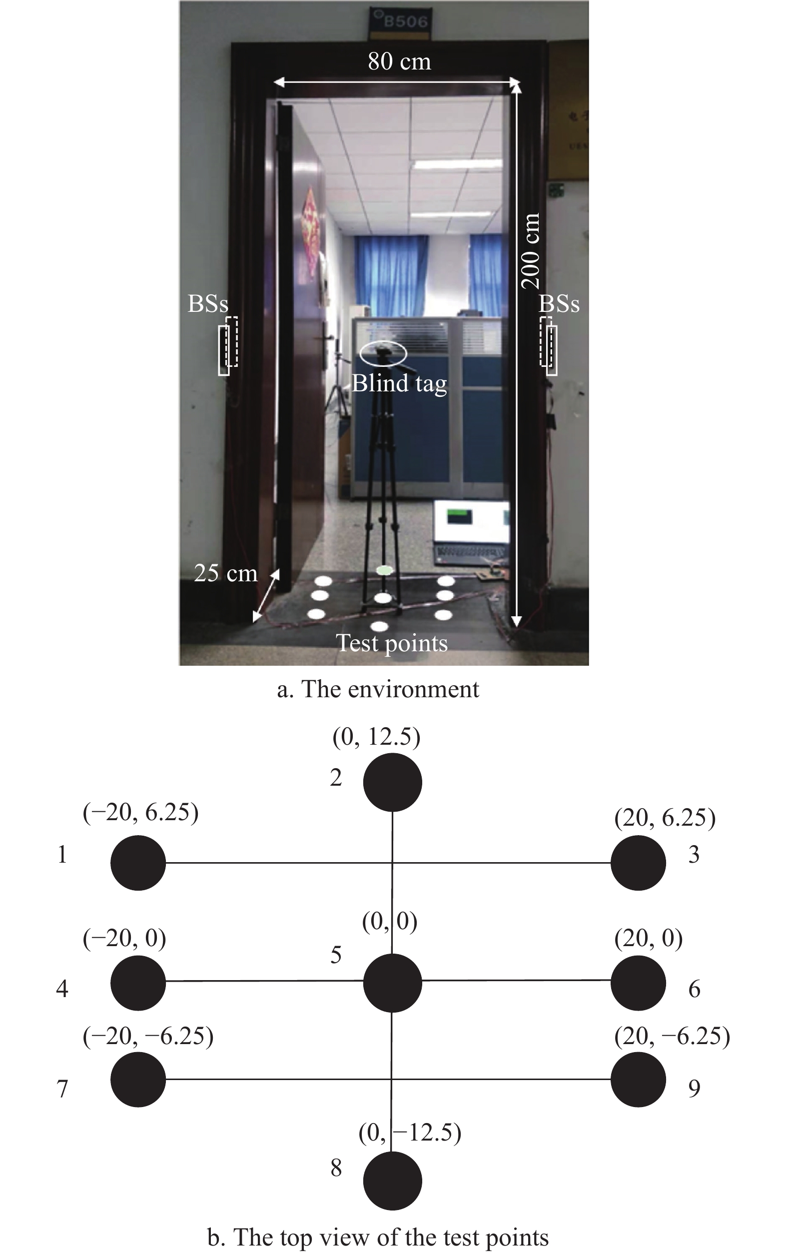
The experiment was carried on near the door of a laboratory in the school, and the size of the door is 80 cm × 25 cm × 200 cm. The position of the 4 BSs is shown in Fig. 6a. All BSs are 125 kHz low-frequency transmitting antennas and RFID tags are semi-active, Semi-active tags only work in the active area (i.e. near the detection area), which reduces power consumption and improves tag endurance. The type of RFID tag used in this paper is the ATA5702 tag.
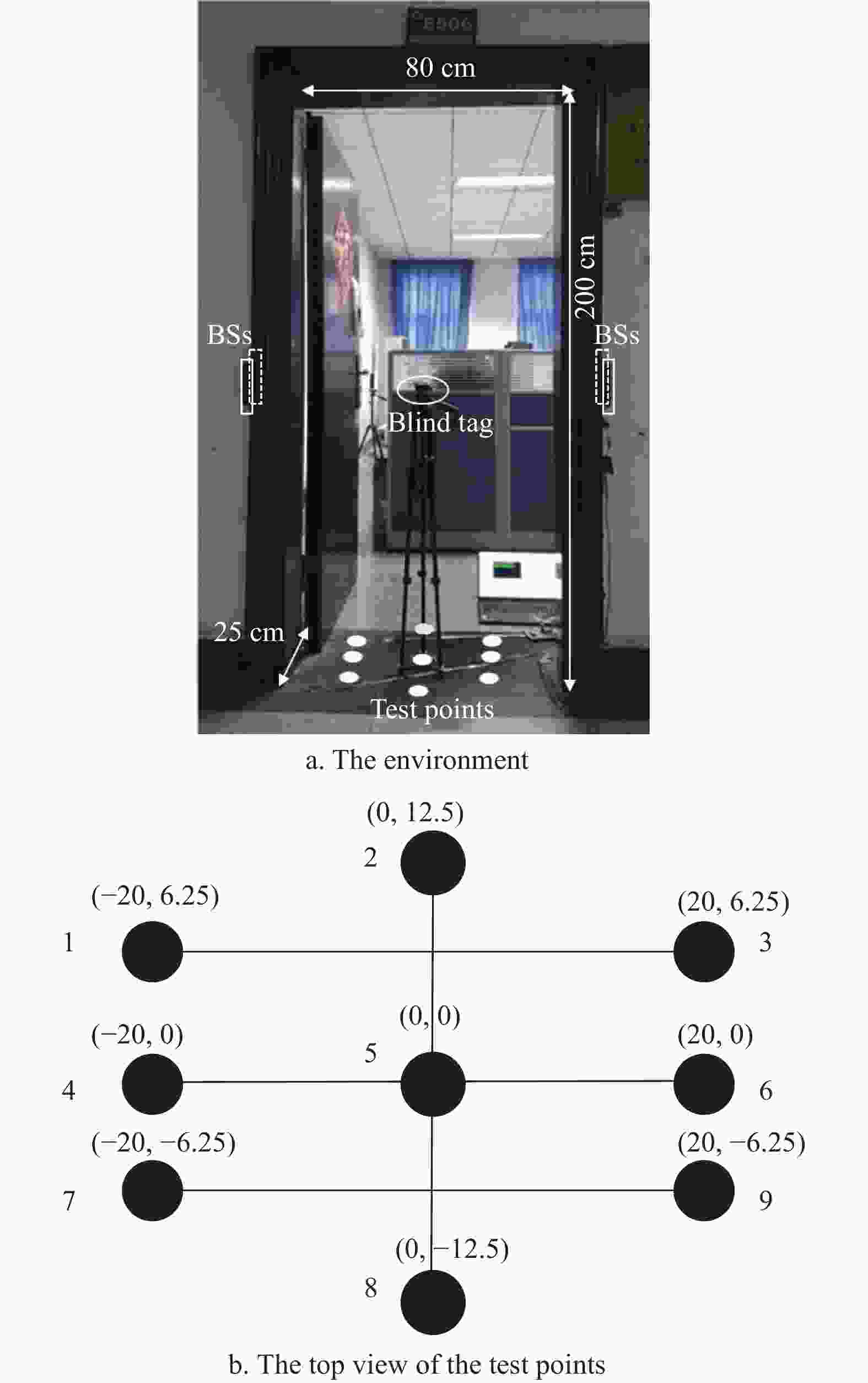
Figure 6. Experimental environment
To verify the accuracy and stability of this detection algorithm under metal interference, especially in the middle area of the entrance/exit, the experiment selected five different angles
$\alpha $ , and$\alpha $ =[0°, 45°, 60°, 90°, 120°] respectively, where$ \alpha$ =0° indicates that the metal door is completely closed. Then, 9 test points are chosen in the middle of the entry/exit. The top view of test points is shown in Fig. 6b. Among them, the 5th test point is the origin and is located in the exact middle of the detection area. Then, the blind tag will be placed on every test point. -
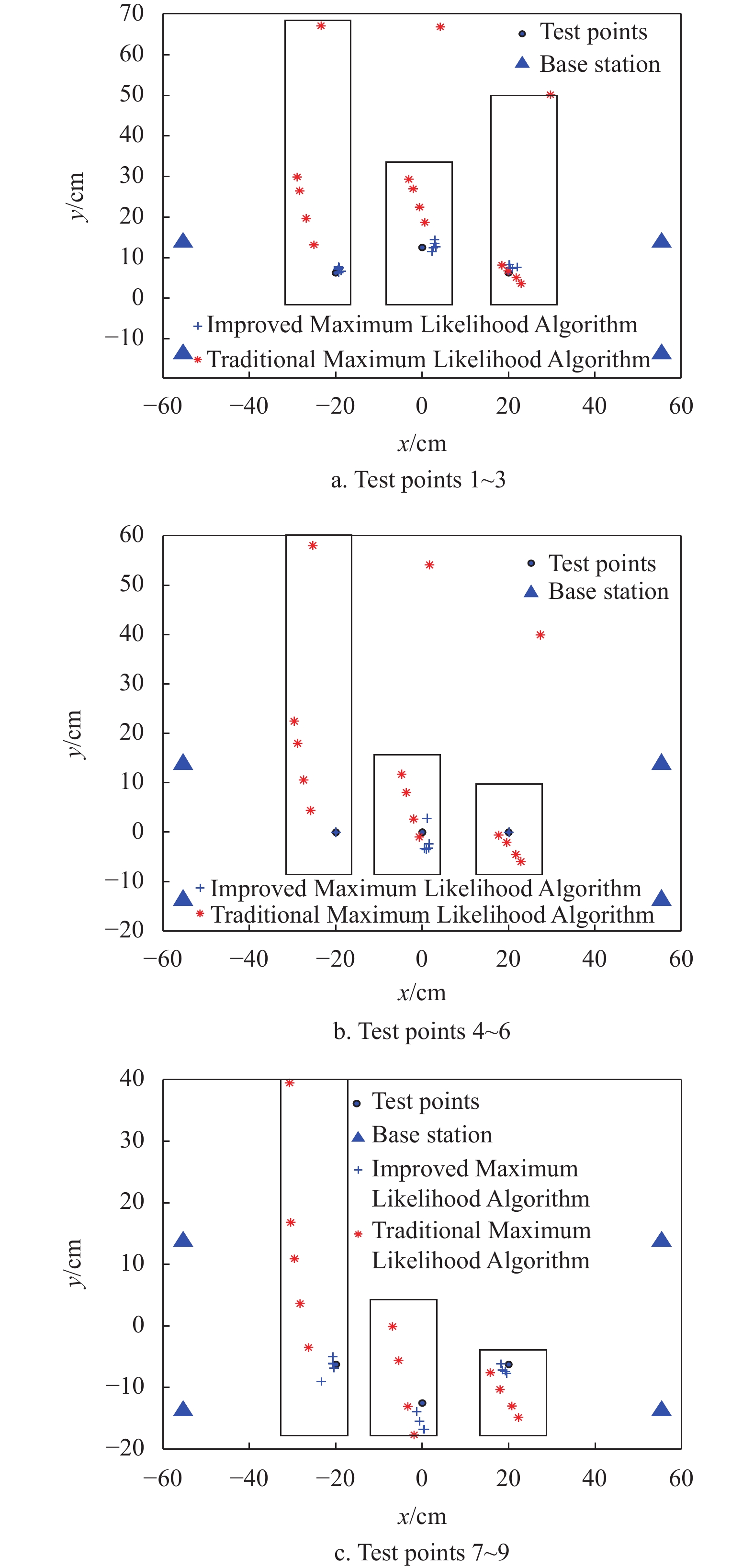
For each test point, five results under five different angles have been obtained. The experiment focuses on comparing the performance between the traditional ML and the improved ML in a dynamic environment. The comparison is shown in Fig. 7.
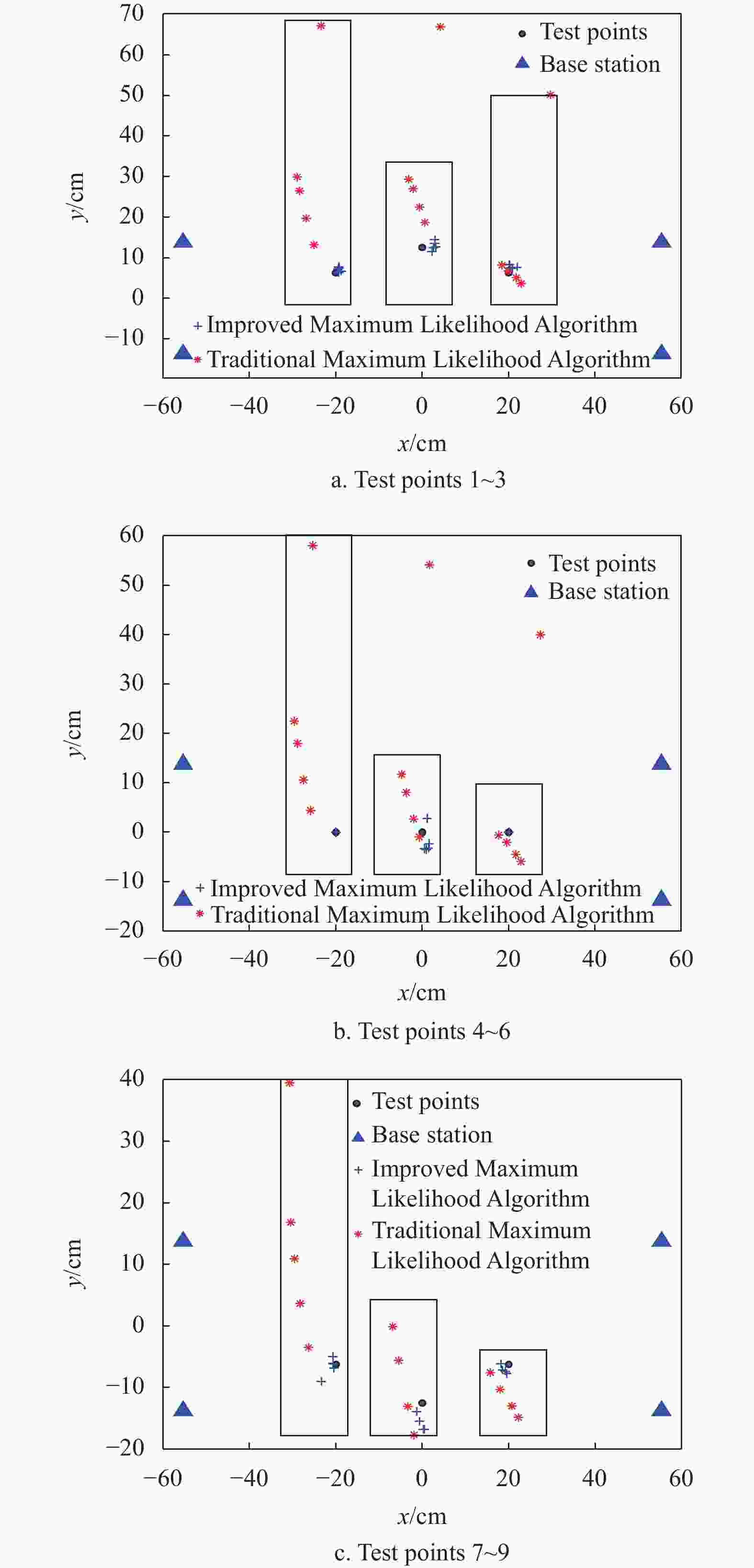
Figure 7. Comparison of the two algorithms in different
$\alpha $ It can be seen from Fig. 7 that for all test points, the result of the improved ML is more focused and consistent with the real position of test points than that of the traditional ML. The three rectangular boxes in Fig. 7 represent the range of the estimated positions of a test point. This indicates that the improved positioning algorithm has a better position effect. For test points 7~9, the reason for the dispersion of the positioning accuracy is that there are some errors in the fitting curves of the nearby reference tags (
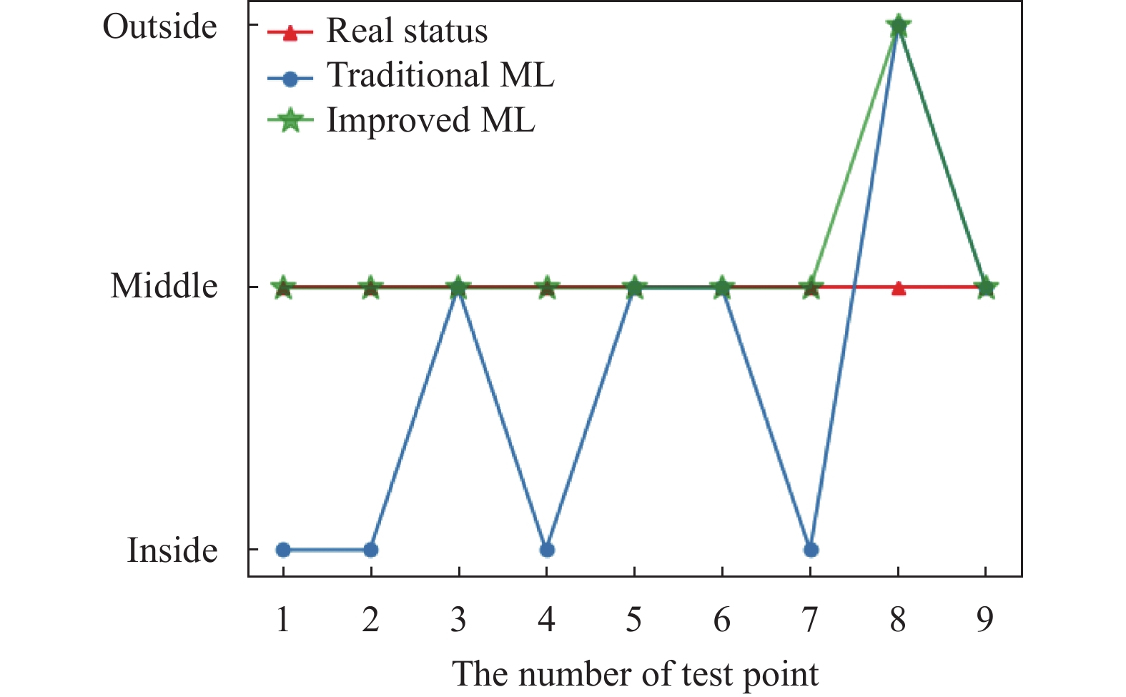
$ {f_{i,m}}({d_{{\rm{ev}}}}) $ in section 2.2), resulting in incomplete ranging correction.Moreover, the above positioning results are used for access detection to obtain the access status of the blind tags at different test points (in Fig. 8).
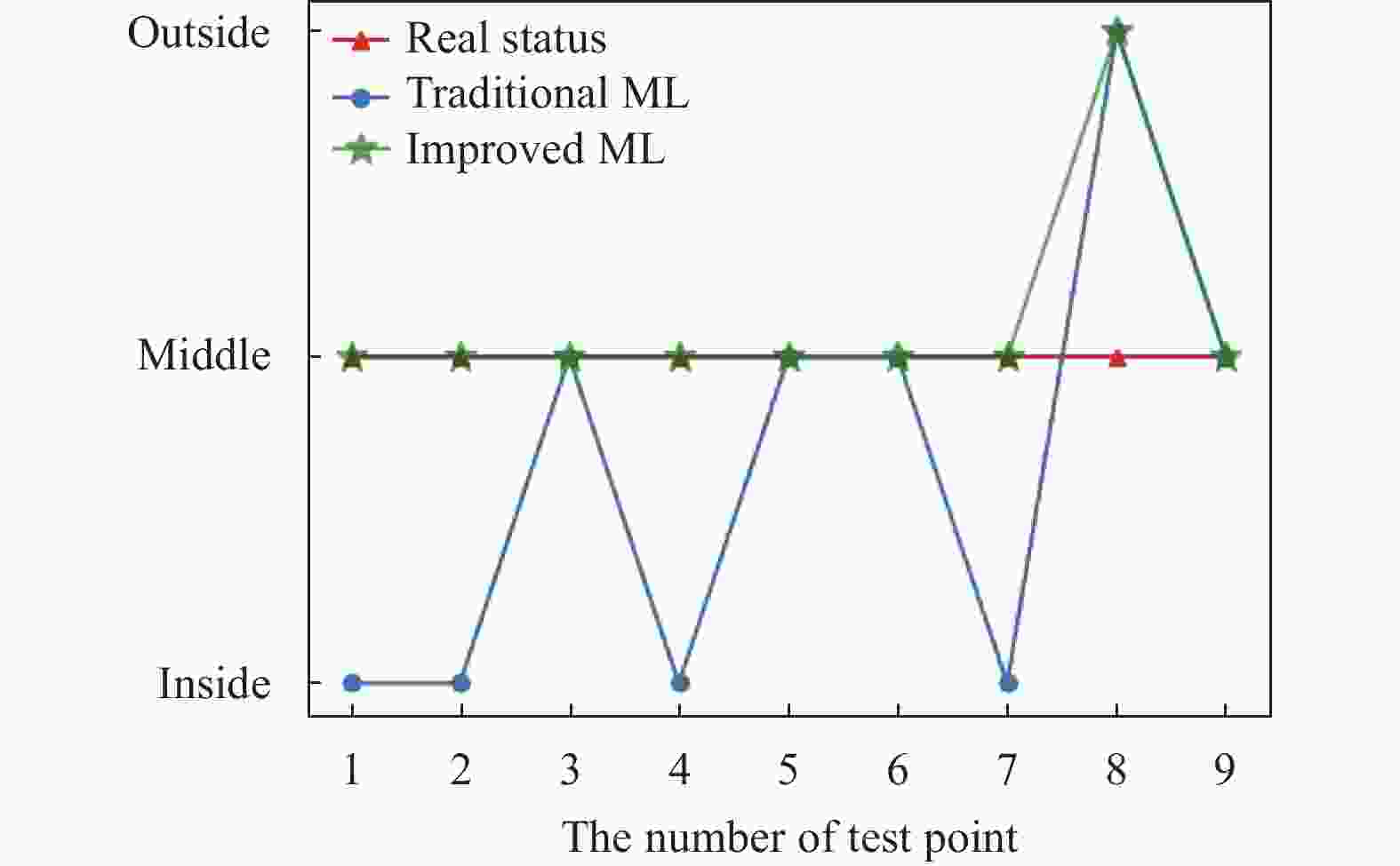
Figure 8. The detection results
For the 9 test points, the detection accuracy of the improved ML algorithm is higher than that of the traditional ML algorithm.
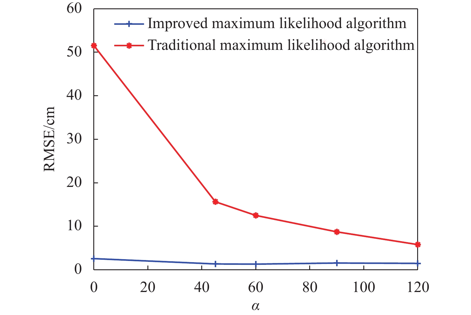
In this paper, RMSE (root mean square error) is chosen as the performance index of the positioning algorithm, which is defined as follows:
$$ {\rm{RMSE}} = \sqrt {\frac{1}{L}\sum\limits_{i = 0}^L {[{{({x_i} - {{\hat x}_i})}^2} + {{({y_i} - {{\hat y}_i})}^2}]} } \; $$ (14) where
$L$ is the number of test points, and$({x_i},{y_i})$ is the real position, and$({\hat x_i},{\hat y_i})$ is the estimated position.The comparison of the positioning error between the traditional ML method and the improved ML method based on RMSE is shown in Fig. 9.
Due to metal interference, the average RMSE of the traditional ML algorithm is 20 cm, and the RMSE even reaches 52 cm when
$\alpha {\text{ = }}0^\circ $ . A positioning error with a few tens of centimeters near the entrance/exit will result in a large detection error. The algorithm in this paper can effectively eliminate the influence of the metal environment on the RSSI ranging, thus indirectly improving the localization effect and stability. After ranging correction, the RMSE of the algorithm is controlled within 3 cm and the localization accuracy is improved by 85%. Compared with the traditional ML algorithm, the improved positioning algorithm has significantly improved both the positioning accuracy and the stability, resulting in stable and accurate detection.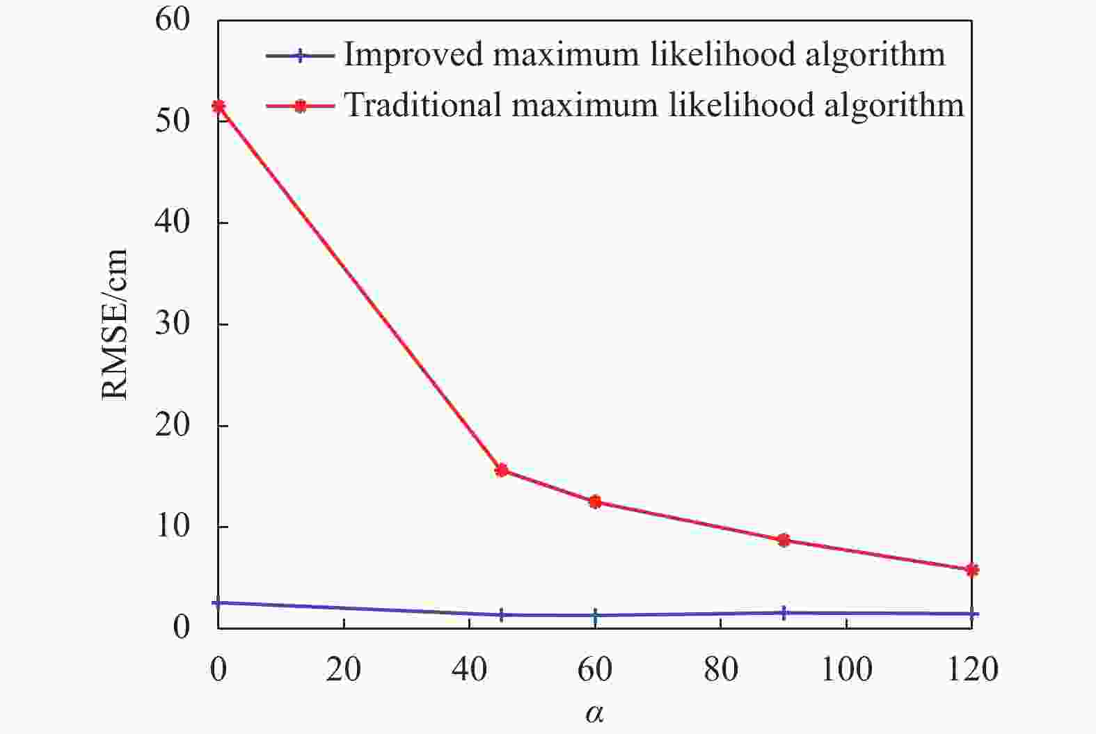
Figure 9. The comparison of algorithm errors
-
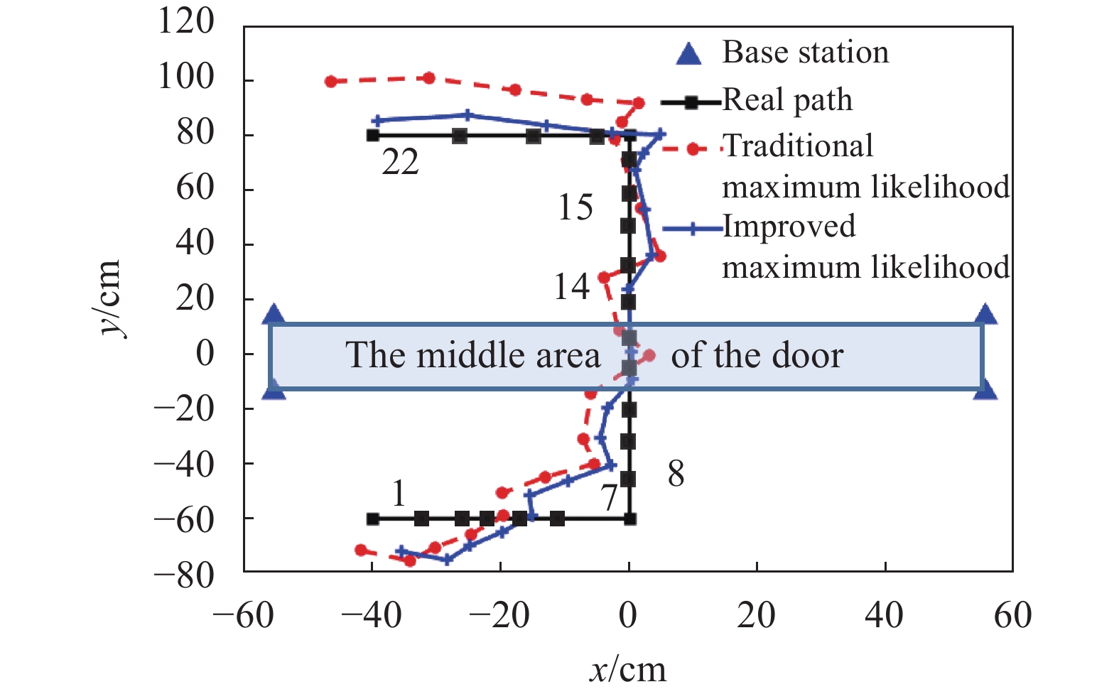
Furthermore, the positioning algorithm is applied to dynamic positioning, and a person carries the RFID tag to enter and exit the door according to the planned trajectory when
$\alpha $ =90° (in Fig. 10). Compared with the traditional ML algorithm, the estimation trajectory of the improved ML algorithm is closer to the actual trajectory of the person from an overall perspective, especially in the middle area of the entry/exit, e.g. at (0,0). The positioning effect of this area is the key to the detection effect for the access detection system. Table 1 shows the positioning performance of all sampling points under the RMSE criterion. Compared with the traditional ML algorithm, the improved ML algorithm in this paper is with smaller positioning errors and higher accuracy in real-time position.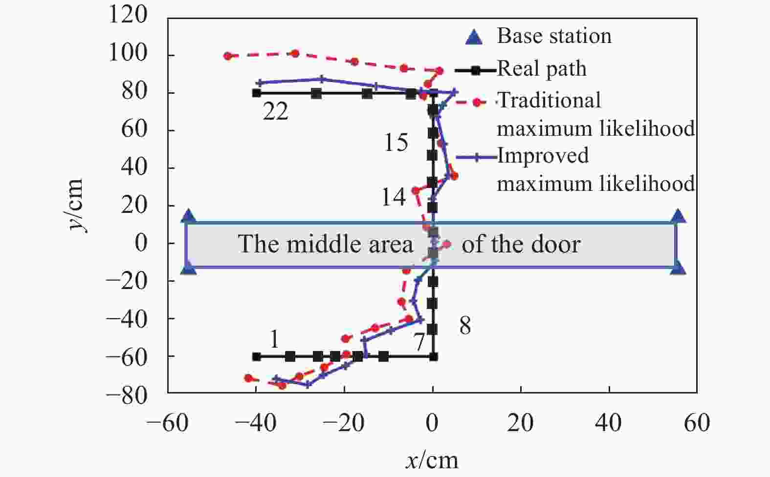
Figure 10. Comparison of real-time position.
Table 1. Positioning performance of traditional ML and improved ML
Sampling points Positioning
algorithmAvg.
RMSEx/cmAvg.
RMSEy/cmAvg.
RMSE/cmPoints 1~7 Traditional ML
Improved ML6.43
4.4710.52
10.0112.33
11.15Points 8~14 Traditional ML
Improved ML4.58
1.935.41
2.147.08
2.88Points 15~22 Traditional ML
Improved ML3.05
2.0816
5.0716.29
5.48 -
The effectiveness of the detection technology will be verified in the access detection system. Meanwhile, two entry and exit strategies are designed as shown in Table 2.
Table 2. Entry and exit strategies
No. Description 1 Walk from the outside of the detection area into the inside, then walk from the inside to the outside. 2 Walk from the inside of the detection area into the outside, then walk from the outside to the inside In this experiment, the subject is required to walk 100 times for every strategy when
$\alpha $ =90°. Therefore, two types of walk strategies are performed 200 times for each subject. Moreover, the tag ID of the first subject is 1, and so on. The red tag represents the outside of the detection area, and the blue tag represents the inside of the detection area. The detection performance is demonstrated in Fig. 11 and Fig. 12. The average detecting accuracy under$\alpha $ = [60°,90°,120° ] is shown in Table 3.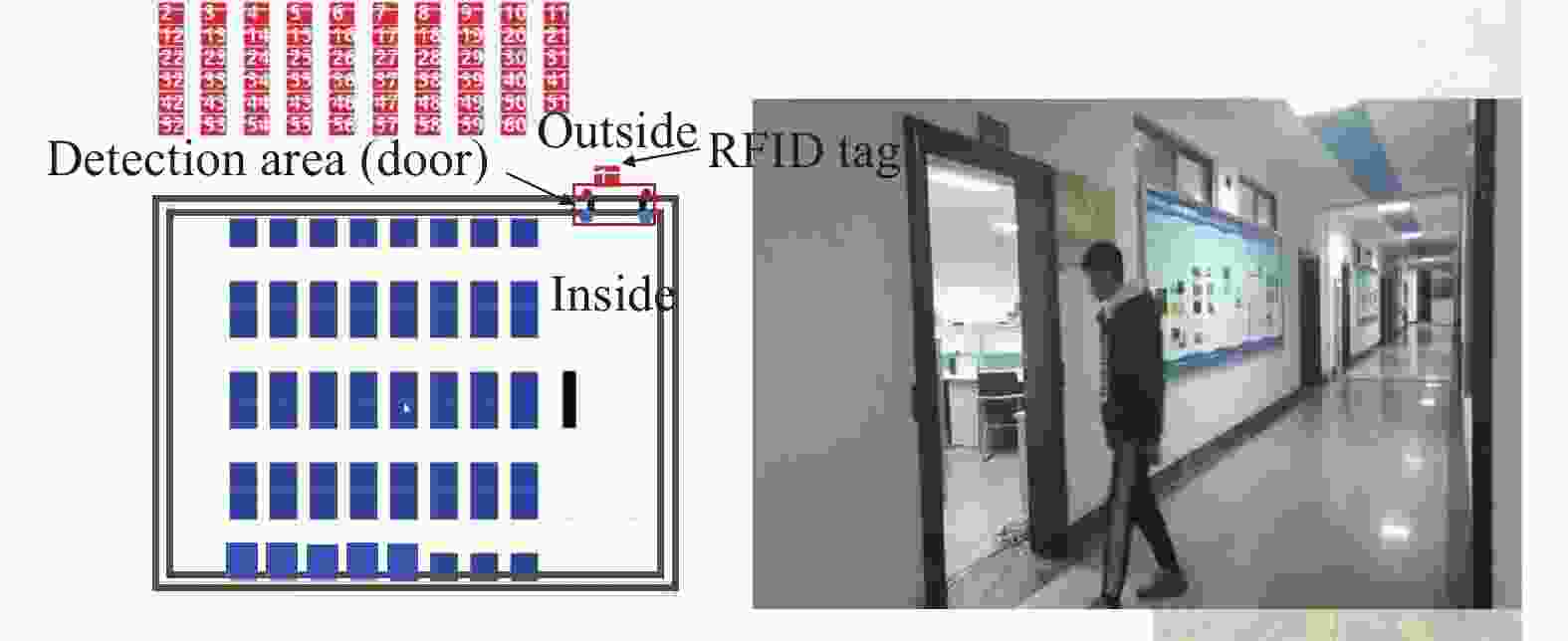
Figure 11. Detection performance on the outside
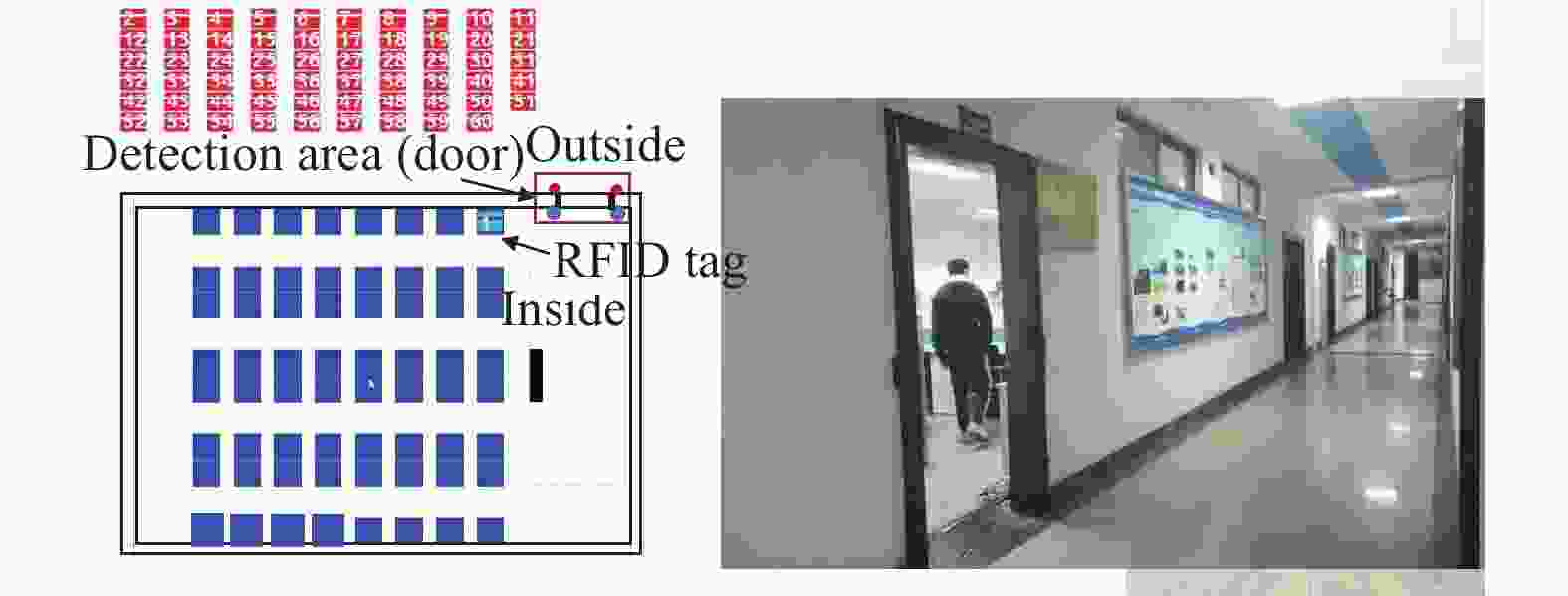
Figure 12. Detection performance on the inside
Table 3. Entry and exit strategies
% Subject Detection accuracy No.1 99 No.2 100 No.3 99.5 No.4 100 It can be seen from Fig. 11 and Fig. 12 that when the subject is outside of the detection area, the tag is also on the outside and shows a red state, and when the subject enters the inside, the tag also enters the inside of the detection area at the same time and the state of the tag converts into blue. This indicates that the detection results are as expected.
For the two common entry and exit strategies, the accuracy of detecting people entering /exiting is up to 99% or more. This verifies that the access detection technology has a high detection accuracy and it is enough for application.
-
The existing RSSI-based positioning algorithms have the disadvantages of low positioning accuracy and poor stability due to the metal interferce, resulting in detection errors. An access detection method with an accurate positioning algorithm based on LF RFID is proposed in this paper. The correction fingerprint database is established, which can correct the ranging error in the positioning stage, and then the positioning effect is better. In the positioning experiment, compared with the traditional ML, the improved ML method has higher positioning accuracy and better algorithm stability, which can reach 3 cm and achieve an 85% improvement in localization accuracy generally. In the detection experiment, the proposed access detection technology is also able to accurately detect the real access status of the experimental subject under two walk strategies, which is enough for application because of the detection accuracy of up to 99%. However, considering the spatial inhomogeneity of RSSI and different walk actions, in the future, the accuracy and stability of the detection method will need to be further enhanced.
-
摘要: LF RFID技术的性能易受到复杂环境因素的影响,特别是在金属环境中,会导致检测精度低、稳定性差。为此,提出了一种基于改进的最大似然的准确定位算法的进出检测方法。该定位算法包括训练阶段和定位阶段。在训练阶段,建立了修正指纹数据库,用于修正由于环境因素造成的测距误差;在定位阶段,利用修正后的测距误差,通过最大似然算法来定位目标所携带的标签位置,以检测目标的进出状态。实验结果表明,该算法的检测精度可以达到3 cm,在设定的两种行走策略下,目标的进出检测精度可以达到99%以上,满足实际应用需要。Abstract: The low frequency radio frequency identification (LF RFID)-based detection technology is popular for access detection systems because it is convenient and low-cost. However, the performance of LF RFID technology is easily affected by complex environmental factors, especially in the metal environment, leading to low detection accuracy and poor stability. To tackle this problem, we propose an access detection method with an accurate positioning algorithm based on improved maximum likelihood in this paper. The positioning algorithm consists of two stages: training stage and positioning stage. In the training stage, a correction fingerprint database is established. The database is used to correct the ranging error due to environmental factors. In the positioning stage, after correcting the ranging measurement error, the maximum likelihood algorithm is used to locate tags carried by subjects for detecting the entry/exit status. Some experimental results show that the detection accuracy can reach 3 cm and the accuracy of detecting entering/exiting status under two walk strategies is up to 99% or more, which is enough for application.
-
Key words:
- access detection /
- fingerprint correction database /
- LF RFID /
- maximum likelihood
-
Table 1. Positioning performance of traditional ML and improved ML
Sampling points Positioning
algorithmAvg.
RMSEx/cmAvg.
RMSEy/cmAvg.
RMSE/cmPoints 1~7 Traditional ML
Improved ML6.43
4.4710.52
10.0112.33
11.15Points 8~14 Traditional ML
Improved ML4.58
1.935.41
2.147.08
2.88Points 15~22 Traditional ML
Improved ML3.05
2.0816
5.0716.29
5.48 下载: 导出CSV
Table 2. Entry and exit strategies
No. Description 1 Walk from the outside of the detection area into the inside, then walk from the inside to the outside. 2 Walk from the inside of the detection area into the outside, then walk from the outside to the inside
下载: 导出CSV
Table 3. Entry and exit strategies
% Subject Detection accuracy No.1 99 No.2 100 No.3 99.5 No.4 100
下载: 导出CSV
-
[1] LUO J, FAN L, LI H. Indoor positioning systems based on visible light communication: State of the art[J]. IEEE Communications Surveys & Tutorials, 2017, 19(4): 2871-2893. [2] BOKA A, MORRIS B. Person recognition for access logging[C]//2019 IEEE 9th Annual Computing and Communication Workshop and Conference (CCWC). [S. l. ]: IEEE, 2019: 933-936. [3] NARMADHA V, APARNA K, KAMALESHWARI J, et al. Integrated power management with automated attendance system[C]//2019 3rd International Conference on Computing and Communications Technologies (ICCCT). Piscataway, NJ: IEEE, 2019: 14-17. [4] AKBAR M S, SARKER P, MANSOOR A T, et al. Face recognition and RFID verified attendance system[C]//2018 International Conference on Computing, Electronics & Communications Engineering (iCCECE). New York, NY: IEEE, 2018: 168-172. [5] BHATTACHARYA S, NAINALA G S, DAS P, et al. Smart attendance monitoring system (SAMS): A face recognition based attendance system for classroom environment[C]//2018 IEEE 18th International Conference on Advanced Learning Technologies (ICALT). New York, NY: IEEE, 2018: 358-360. [6] NI L M, ZHANG D, SOURYAL M R. RFID-based localization and tracking technologies[J]. IEEE Wireless Communications, 2011, 18(2): 45-51. doi: 10.1109/MWC.2011.5751295 [7] YANG J C, LAI C L, SHEU H T, et al. An intelligent automated door control system based on a smart camera[J]. Sensors, 2013, 13(5): 5923-5936. doi: 10.3390/s130505923 [8] LI C, MO L, ZHANG D. Review on UHF RFID localization methods[J]. IEEE Journal of Radio Frequency Identification, 2019, 3(4): 205-215. doi: 10.1109/JRFID.2019.2924346 [9] CHOWDHURY M, GAO J, ISLAM R. Human detection and localization in secure access control by analysing facial features[C]//2016 IEEE 11th Conference on Industrial Electronics and Applications (ICIEA). New York, NY: IEEE, 2016: 1311-1316. [10] ZHAO Y, MENG W, LI Y, et al. System performance analysis of multi-user single-node indoor positioning[C]//2019 Computing, Communications and IoT Applications (ComComAp). New York, NY: IEEE, 2019: 123-128. [11] LI C, TANGHE E, PLETS D, et al. RePos: Relative position estimation of UHF-RFID tags for item-level localization[C]//2019 IEEE International Conference on RFID Technology and Applications (RFID-TA). New York, NY: IEEE, 2019: 357-361. [12] LUO W, DENG X, ZHANG F, et al. Positioning and guiding educational robots by using fingerprints of WiFi and RFID array[J]. EURASIP Journal on Wireless Communications and Networking, 2018(1): 1-11. doi: 10.1186/s13638-017-1011-3 [13] CHEN W. Radio frequency identification technology and applications[D]. Turku: Turku University of Applied Sciences, 2015. [14] LEHPAMER H. RFID design principles[M]. Norwood MA: Artech House, 2012. [15] XIE L, LU S. Radio frequency identification technology [M]. Beijing: Science Press, 2016. [16] KONG H, YU B. A moving object indoor tracking model based on semiactive RFID[J]. Mathematical Problems in Engineering, 2018, 2018(1): 1-7. [17] RJEIB H D, ALI N S, AL FARAWN A, et al. Attendance and information system using RFID and web-based application for academic sector[J]. International Journal of Advanced Computer Science and Applications, 2018, 9(1): 266-274. [18] HE X. Research and design of vehicle keyless entry system[D]. Beijing: Tsinghua University, 2012. [19] SUBEDI S, PAULS E, ZHANG Y D. Accurate localization and tracking of a passive RFID reader based on RSSI measurements[J]. IEEE Journal of Radio Frequency Identification, 2017, 1(2): 144-154. doi: 10.1109/JRFID.2017.2765618 [20] LI Y. Research and implementation of indoor positioning technology based on RFID[D]. Nanjing: Nanjing University of Posts and Telecommunications, 2021. [21] MA Q, LI X, LI G, et al. MRLIHT: Mobile RFID-based localization for indoor human tracking[J]. Sensors, 2020, 20(6): 1711. doi: 10.3390/s20061711 [22] PARK J, KIM Y J, LEE B K. Passive radio-frequency identification tag-based indoor localization in multi-stacking racks for warehousing[J]. Applied Sciences, 2020, 10(10): 3623. doi: 10.3390/app10103623 [23] WANG J, DHANAPAL R K, RAMAKRISHNAN P, et al. Active RFID based indoor localization[C]//2019 22th International Conference on Information Fusion (FUSION). New York, NY: IEEE, 2019: 1-7. [24] ZHAO C, WANG B. A MLE-PSO indoor localization algorithm based on RSSI[C]//2017 36th Chinese Control Conference (CCC). Piscataway, NJ: IEEE, 2017: 6011-6015. [25] XU X L. Internet of things indoor positioning technology [M]. Beijing: Electronic Industry Press, 2017. [26] XIANG Z, SONG S, CHEN J, et al. A wireless LAN-based indoor positioning technology[J]. IBM Journal of Research and Development, 2004, 48(5/6): 617-626. doi: 10.1147/rd.485.0617 [27] Occupational Safety and Health Administration. Electromagnetic radiation and how it affects your instruments. near field vs. far field[EB/OL]. [2021-10-22]. https://www.osha.gov/SLTC/radiofrequencyradiation/electromagnetic_fieldmemo/electromagnetic.html. [28] HENDRY M. Near field communications technology and applications[M]. Cambridge: Cambridge University Press, 2015. [29] RUI Q, WEI W, WANG H, et al. 3D maximum likelihood estimation positioning algorithm based on RSSI ranging[C]//IEEE 2nd Advanced Information Technology. New York, NY: IEEE, 2017: 1311-1314. -

 点击查看大图
图(12) / 表(3)
计量
- 文章访问数: 3629
- HTML全文浏览量: 990
- PDF下载量: 45
- 被引次数: 0