ISSN
ISSN 


-
作为无线通信系统中的重要组件,可调带通滤波器由于其灵活性高、尺寸紧凑等优点引起了人们的广泛关注[1-2]。可调滤波器的调谐方案众多[3],以变容二极管作为调谐器件的可调方案具有调谐速度快、制造成本低的优点,成为众多可调方案中应用最为广泛的一种[4-5]。文献[6-10]中提出了一系列基于均匀阻抗谐振器的频率可调带通滤波器设计,通过引入源和负载端耦合,在通带两侧产生两个传输零点,改善了滤波器的选择性。为了实现滤波器频率及带宽同时可调,文献[11-13]中在均匀阻抗谐振器之间增加变容二极管或PIN开关,实现谐振器间耦合系数可调。除了均匀阻抗谐振器,基于变容二极管加载的阶跃阻抗谐振器由于其调谐范围宽和尺寸紧凑的优点,在文献[14-17]中也被用于频率可调滤波器的设计,除了这些基于耦合谐振器的滤波器外,文献[18-21]中还介绍了基于双模谐振器的频率可调滤波器设计,与基于耦合谐振腔的滤波器相比,这些滤波器通常具有更加紧凑的尺寸。然而,上述介绍的频率可调滤波器由于其阶数较低,只有两个极点,其选择性比较差。为改善滤波器的选择性,文献[23-26]中提出了一些基于均匀阻抗谐振器的四阶可调滤波器设计,上述滤波器的选择性显著增强,但是这些滤波器的调谐范围较窄。因此,为改善高选择性频率可调滤波器的调谐范围,本文采用VL-SIR设计一款4阶4零点的频率可调滤波器,该滤波器采用级联四元组(Cascaded Quadruplet, CQ)拓扑结构,通过引入交叉耦合,在通带近端产生一对传输零点,显著改善滤波器的选择性,同时引入源和负载端耦合,在通带远端产生一对交叉零点,改善了阻带抑制性。谐振器之间采用频变耦合结构,实现了频率调谐过程中绝对带宽保持稳定。
-
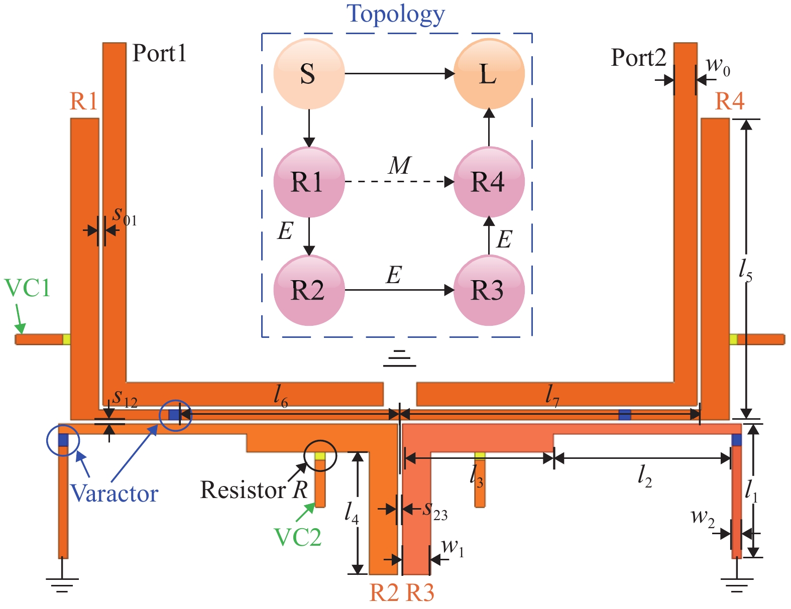
图1为所提出的可调滤波器的结构示意图。滤波器由四个阶跃阻抗谐振器(R1,R2,R3,R4)和输入/输出馈电微带线组成。变容二极管作为调谐元件的加载在阶跃阻抗谐振器的高阻抗线路中,通过改变直流偏置电压VC1/VC2来改变变容二极管的有效电容,实现谐振器谐振频率可调谐。4个VL-SIRs通过直径为0.4 mm的金属过孔连接到地。滤波器具有左右对称结构,有助于简化设计和优化过程。
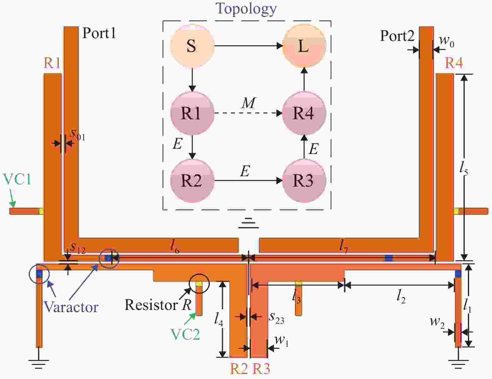
图 1 滤波器拓扑及结构示意图
滤波器拓扑为经典CQ结构,如图1中框图所示。基于经典滤波器理论[27],在谐振器R1和R4之间引入感性交叉耦合可以在通带近端产生两个传输零点,从而改善滤波器的选择性,零点距离通带越近,滤波器矩形系数越小。此外,在滤波器源和负载端引入容性交叉耦合,还可以在通带远端产生两个传输零点,以提高阻带的抑制水平。
滤波器设计指标如下,频率调谐范围0.8~1.1 GHz,3dB绝对带宽50 MHz,回波损耗:20 dB,传输零点位置:±1.7和±20(归一化频率[28])
使用文献[21]中所介绍的耦合矩阵综合方法得到(N+2)阶归一化耦合矩阵M:
$$ \left[ M \right] = \left[ {\begin{array}{*{20}{c}} 0&{1.02}&0&0&{\text{0}}&{0.000{\text{6}}} \\ {1.02}&0&{0.8{\text{5}}}&0&{ - 0.{\text{25}}}&0 \\ 0&{0.8{\text{5}}}&0&{0.{\text{8}}}&0&0 \\ 0&0&{0.{\text{8}}}&0&{0.8{\text{5}}}&0 \\ 0&{ - 0.{\text{25}}}&0&{0.8{\text{5}}}&0&{1.02} \\ {0.{\text{0006}}}&{\text{0}}&0&0&{1.02}&0 \end{array}} \right] $$ (1) 则滤波器耦合矩阵[m]和外部品质因数Qe可由式(2)和(3)计算得到,在式(2)、(3)中,fo为可调滤波器的中心频率,ABW为滤波器绝对带宽,Ms1为滤波器源端与第一个谐振器之间的归一化耦合系数,其中,fo= 0.8~1.1 GHz,ABW=50 MHz。
$$ \left[m\right]=\left[M\right]·\frac{ABW}{{f}_{o}} $$ (2) $$ {\text{Q}}_{e}=\frac{{f}_{o}}{{M}_{\text{S}1}^{\text{2}}·ABW} $$ (3) 根据式(2)和(3)计算得到理论耦合系数和外部品质因数Qe与谐振频率的关系曲线如图2所示,其中,m_sl为源端和负载端的耦合系数。由下图可知,在滤波器中心频率调谐过程中,为保持滤波器绝对带宽稳定不变,谐振器间的耦合系数应该与中心频率成反比,外部品质因数与中心频率成正比。

图 2 理论耦合系数和外部品质因数
-
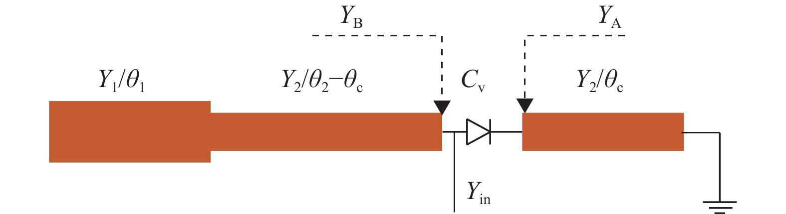
变容二极管加载的阶跃阻抗谐振器结构如图3所示,谐振器由一段低阻抗线和一段高阻抗线串联而成,低阻抗线和高阻抗线的特性导纳和电长度分别为Y1, Y2和θ1, θ2。高阻抗线一端接地,低阻抗线一端为开路状态。在高阻抗线中间加载变容二极管,距离高阻抗线接地端的距离为θc,变容二极管的有效电容用Cv表示。此外,VL-SIR的电长度比和特性导纳比用α和β表示,
$ \alpha {\text{ = }}{{{\theta _{\text{2}}}} \mathord{\left/ {\vphantom {{{\theta _{\text{2}}}} {({\theta _{\text{1}}} + {\theta _{\text{2}}})}}} \right. } {({\theta _{\text{1}}} + {\theta _{\text{2}}})}} $ ,$ \beta {\text{ = }}{{{Y_{\text{1}}}} \mathord{\left/ {\vphantom {{{Y_{\text{1}}}} {{Y_{\text{2}}}}}} \right. } {{Y_{\text{2}}}}} $ 。
图 3 变容管加载的阶跃阻抗谐振器结构示意图
根据传输线理论[28],输入导纳Yin可以通过以下式(4)-式(6)计算。谐振器的谐振条件是输入导纳的虚部必须为零[29],即 Im(Yin) = 0,因此式(3)-式(5)可用于计算VL-SIR的谐振频率:
$$ {Y_A} = \frac{{{Y_2}}}{{jtan{\theta _c}}} $$ (4) $$ {Y_B} = \frac{{j{Y_1}{Y_2}tan{\theta _1} + jY_{\text{2}}^{\text{2}}tan({\theta _{\text{2}}} - {\theta _{\text{c}}})}}{{{Y_2}{\text{ - }}j{Y_1}tan{\theta _1}tan({\theta _{\text{2}}} - {\theta _{\text{c}}})}} $$ (5) $$ {Y_{in}} = \frac{{jw{C_v}{Y_A}}}{{{Y_A} + jw{C_v}}} + {Y_B} $$ (6) 调谐范围(Tuning Range, TR)是频率可调滤波器的关键指标,调谐范围TR定义如式(7)所示。在(7)中,f(Cv_min)和f(Cv_max)分别表示当有效电容Cv为最小值和最大值时VL-SIR的谐振频率:
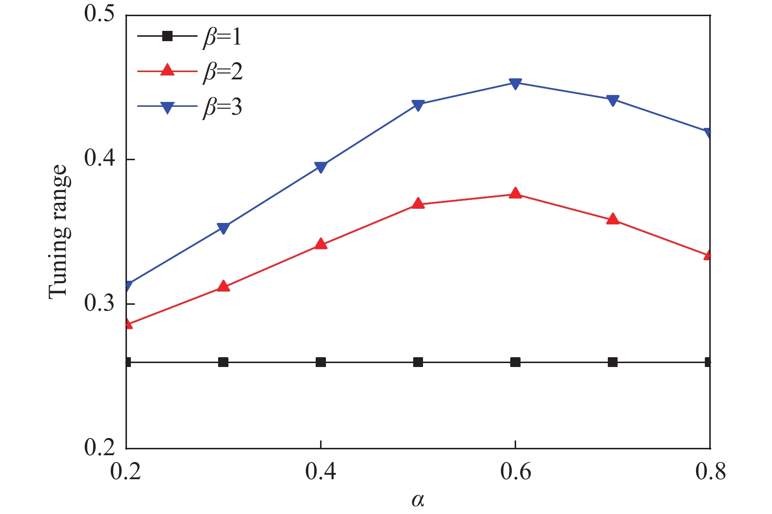
$$ TR = \frac{{f({C_{v\_\min }}) - f({C_{v\_\max }})}}{{{{(f({C_{v\_\min }}) + f({C_{v\_\max }}))} \mathord{\left/ {\vphantom {{(f({C_{v\_\min }}) + f({C_{v\_\max }}))} 2}} \right. } 2}}} $$ (7) 不同特性导纳比β下调谐范围和电长度比α之间的关系如图4所示,此时,Y1=0.03S, θ1+θ2=180°,变容二级管加载位置θc=20°,电长度参考频率为1 GHz。当特性导纳β为1时,谐振器为均匀阻抗谐振器,当电长度比α改变时,调谐范围TR保持不变。当特性导纳β不为1时,随着电长度比α的增加,调谐范围TR先增大后减小,当电长度比α为0.6时,调谐范围TR达到最大值。随着特性导纳β增加,调谐范围TR也会变宽,这意味着与均匀阻抗谐振器相比,阶跃阻抗谐振器可以实现更宽的调谐范围。

图 4 调谐范围随电长度比变化曲线
基于以上分析,与均匀阻抗谐振器相比,所提出的VL-SIR可以实现更宽的调谐范围。因此,本文采用VL-SIR来实现具有高选择性和恒定绝对带宽的频率可调四阶带通滤波器。
-
为了保持滤波器绝对带宽在频率调谐过程中稳定不变,谐振器之间的耦合系数需要与中心频率保持反比关系,而输入和输出端口的外部品质因数需要与中心频率保持正比关系[30]。因此,谐振器之间以及馈电结构的频变耦合特性是实现稳定绝对带宽的关键。本节采用商业软件高级设计系统(ADS)对谐振器之间以及馈电耦合结构的耦合特性进行仿真分析,仿真所用介质基板为Rogers 5880(相对介电常数εr = 2.2、厚度h=0.787 mm)。
-
基于VL-SIR的电耦合频变耦合结构如图5所示。对于变容二极管加载的阶跃阻抗谐振器,谐振器的开路点是电场的最大位置,随着与VL-SIR开路点的距离越来越大,电场强度会越来越小,而磁场强度会越来越大,因此,图5所示频变耦合结构是以电耦合为主的耦合结构。按照图5所示结构在ADS中建立仿真模型,相关结构参数为w1=2 mm, w2=1 mm, l1=10 mm, l2=20 mm, l3+l4=45 mm。

图 5 频变电耦合结构示意图
图6为频变耦合结构在不同耦合缝隙宽度s和变容二极管加载位置l4时提取的电耦合系数与有效电容Cv的变化关系曲线。如下图所示,耦合系数随着Cv的增加而变高,而谐振器的谐振频率随着有效电容Cv的增大而减小,因此耦合系数与谐振频率呈反比关系。当l4=15 mm时,对于不同的耦合缝隙宽度s,当耦合缝隙宽度s较大时,耦合系数幅度整体下降,反之,则耦合系数幅度上升。当s=0.1 mm时,对于变容二极管不同的加载位置l4,耦合系数的斜率随着l4的增加而变大。因此,可以通过改变耦合缝隙宽度s和二极管加载位置l4,灵活地调整耦合系数的大小和频变斜率。
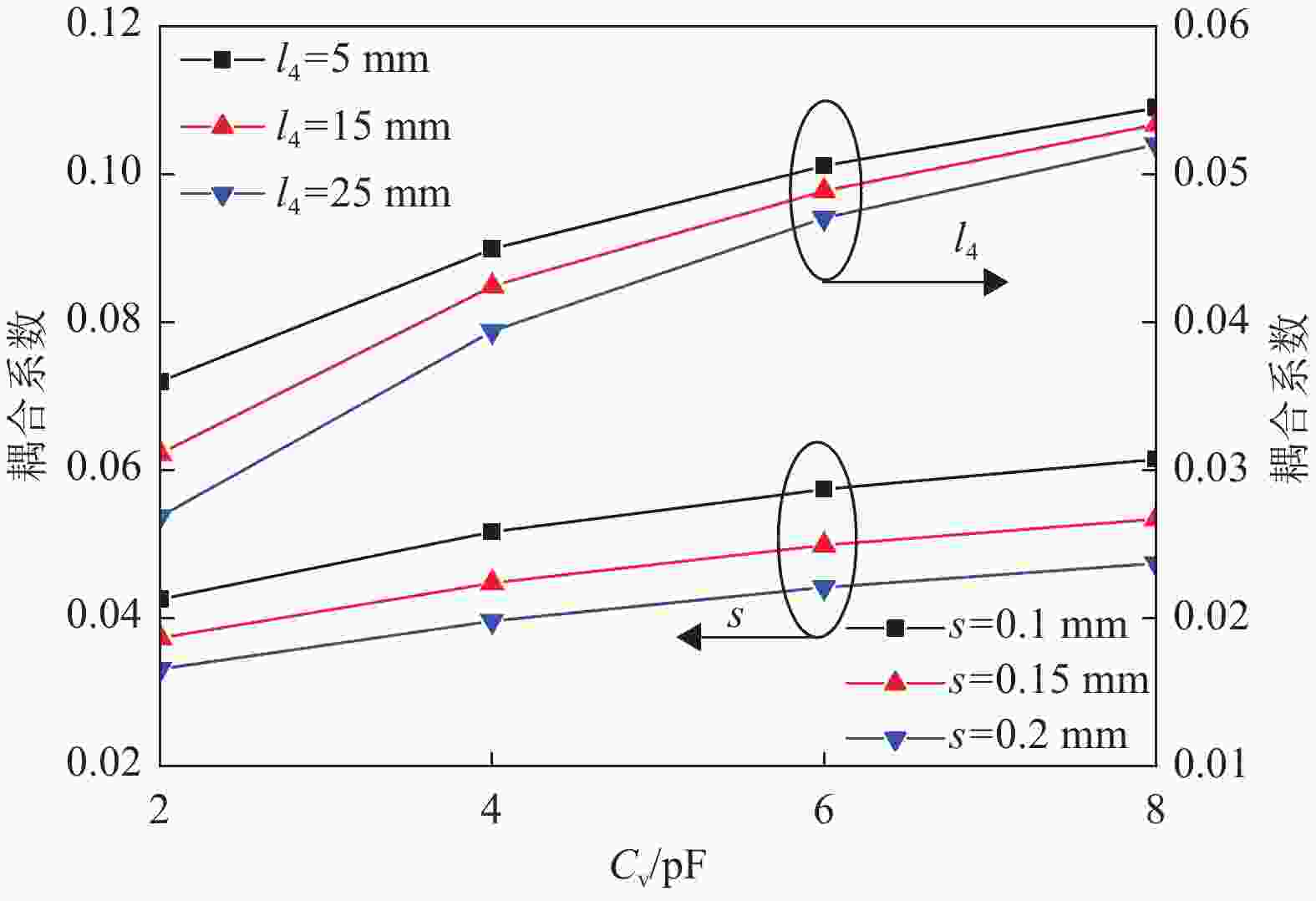
图 6 耦合系数随可变电容变化曲线
-
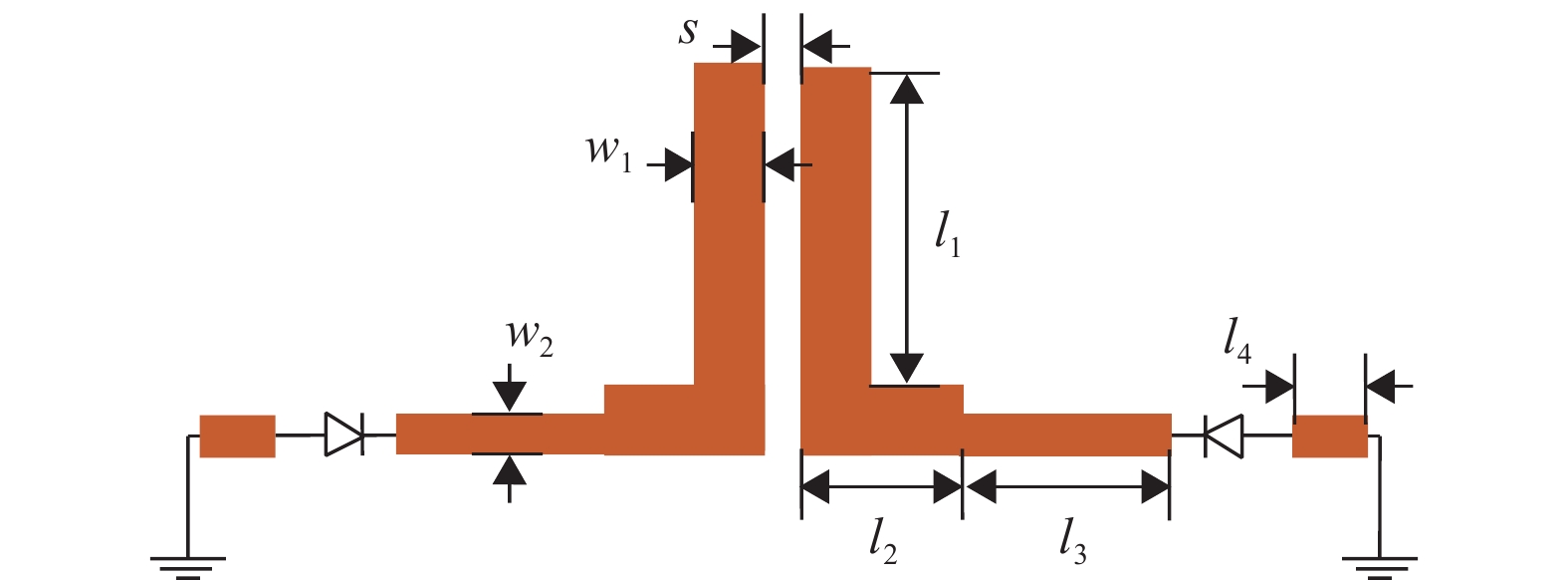
基于VL-SIR的磁耦合频变耦合结构如图7所示,两个变容二极管加载的阶跃阻抗谐振器通过公共短路枝节接地,短路枝节的长度和宽度分别为l4和w4,变容二极管加载位置距离公共接地枝节的距离为l3。对于变容二极管加载的阶跃阻抗谐振器,谐振器的短路点是磁场的最大位置,随着与VL-SIR短路点的距离越来越远,磁场强度会越来越小,而电场强度会越来越大,因此,图7所示频变耦合结构是以磁耦合为主的耦合结构。按照图7所示结构在ADS中建立仿真模型,相关结构参数为w1=2 mm, w2=1 mm, w4=0.4 mm, l1=30 mm, l2+l3=45 mm。
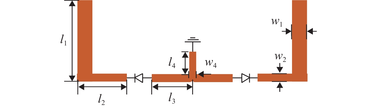
图 7 频变磁耦合结构示意图
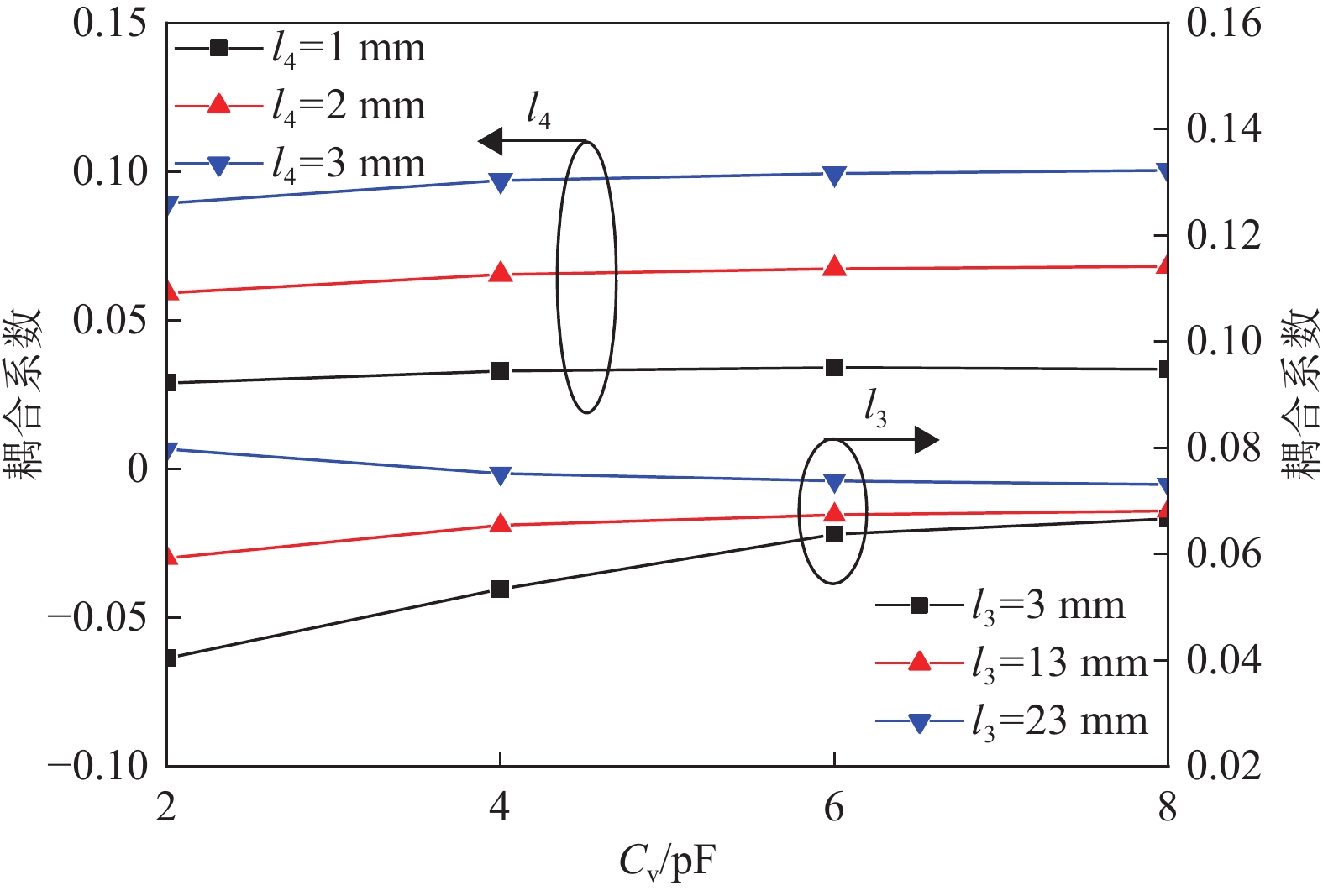
图8为频变耦合结构在不同l3和l4时提取的磁耦合系数与有效电容Cv的变化关系曲线。当l3=13 mm时,对于不同的公共短路枝节长度l4,当l4增大时,耦合系数幅度整体变大,而耦合系数的斜率变化并不明显。当l4=1 mm时,对于变容二极管不同的加载位置l3,耦合系数的斜率随着l3的增加而减小。因此,可以通过改变公共短路枝节长度l4和二极管加载位置l3,灵活地调整耦合系数的大小和频变斜率。在本文中,对于R1和R4,公共短路枝节l4是由金属通孔实现的,金属通孔直径可以用来调整耦合系数的大小。
图 8 耦合系数随可变电容变化曲线
-
基于VL-SIR的频变耦合馈电结构如图9所示,谐振器通过缝隙耦合的方式完成馈电,开路耦合枝节长度和宽度分别为l4和w3,通过宽度为s的缝隙与谐振器耦合。按照图9所示结构在ADS中建立仿真模型,相关结构参数为w1=1 mm,w2=2 mm,w3=2.4 mm,l1+l2=45 mm,l3=30 mm。
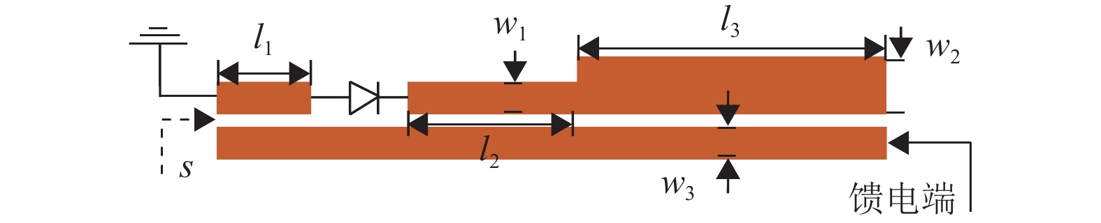
图 9 频变馈电结构示意图
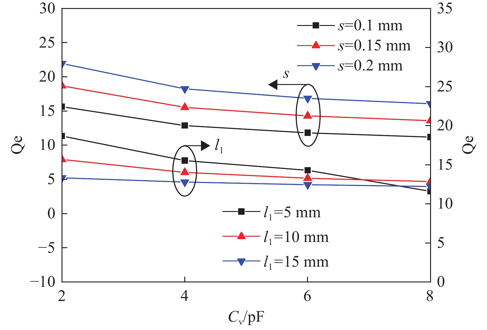
图10为不同耦合缝隙宽度s和变容二极管加载位置l1时外部品质因数Qe与有效电容Cv的变化关系曲线。如图所示,当l1=10 mm时,对比不同的耦合缝隙宽度s,随着耦合缝隙宽度s增大,外部品质因数Qe也整体变大,而Qe的斜率变化并不明显。当s=0.1 mm,对于变容二极管不同的加载位置l1,l1越大,Qe变化斜率的绝对值越小,因此,可以通过改变耦合缝隙宽度s和变容二极管的加载位置l1来调整外部品质因数Qe的大小和频变耦合斜率。
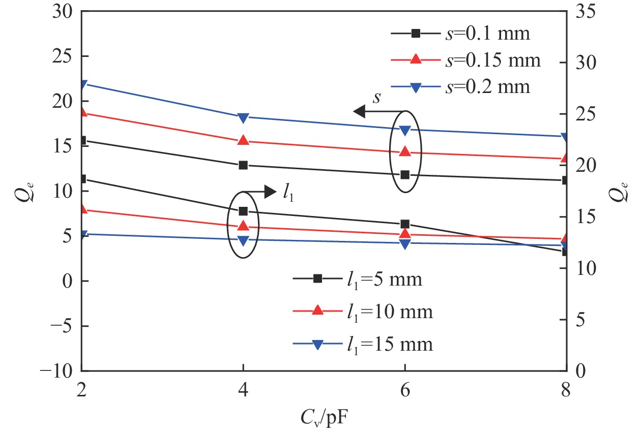
图 10 外部品质因数Qe随电容变化曲线
至此,已经给出了基于VL-SIR的频变电耦合、磁耦合以及馈电结构的频变特性分析,根据上述分析,通过改变相应的结构参数,可以灵活地调整谐振器间的耦合系数以及外部品质因数的大小和频变斜率,这一频变特性对于实现频率可调滤波器的恒定绝对带宽性能至关重要。
-
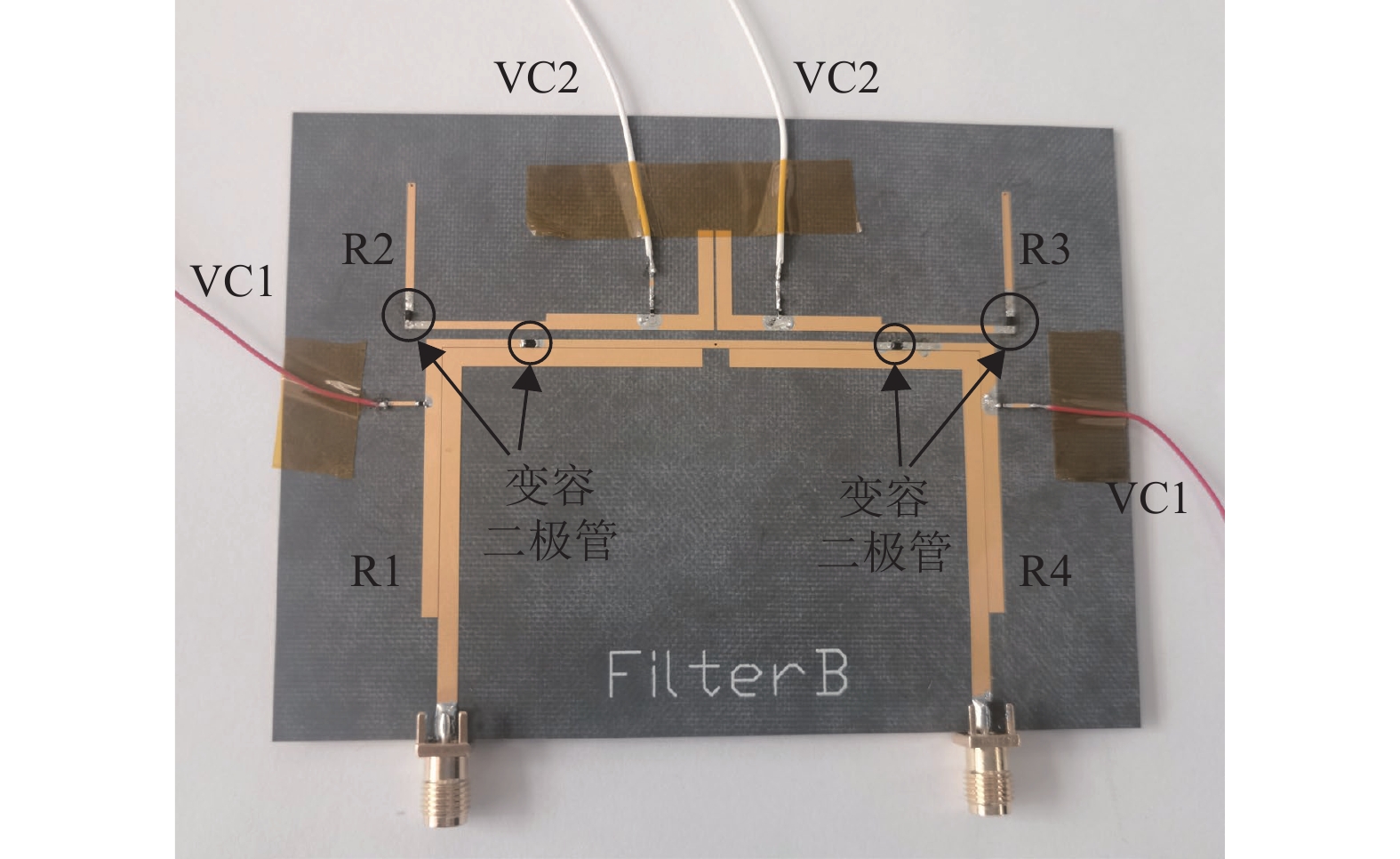
所提出的4阶4零点频率可调带通滤波器加工实物如图11所示,滤波器使用Rogers 5880进行加工,介质基板相对介电常数εr为2.2,厚度为0.787 mm。使用全波仿真软件HFSS对滤波器进行优化和仿真,滤波器最终尺寸为l1=12.1 mm, l2=20.3 mm, l3=13.1 mm, l4=11.2 mm, l5=13.3 mm, l6=23.2 mm, l7=27.4 mm, w0=2.4 mm, w1=2.5 mm, w2=0.9 mm, S01=0.12 mm, S12=1.42 mm, S23=0.46 m,滤波器整体尺寸为46.8 mm × 70 mm。使用Skyworks公司的商用变容二极管管SMV1413-SC79作为调谐器件,该变容二极管电容调谐范围从1.77 pf(30 V)到9.6 pf(0 V)。变容二极管的有效电容可以通过直流偏置电压VC1和VC2进行控制。直流偏置线使用0402封装的470 nH电感与谐振器相连,该扼流电感可以减少偏置电路对谐振器电路的影响。
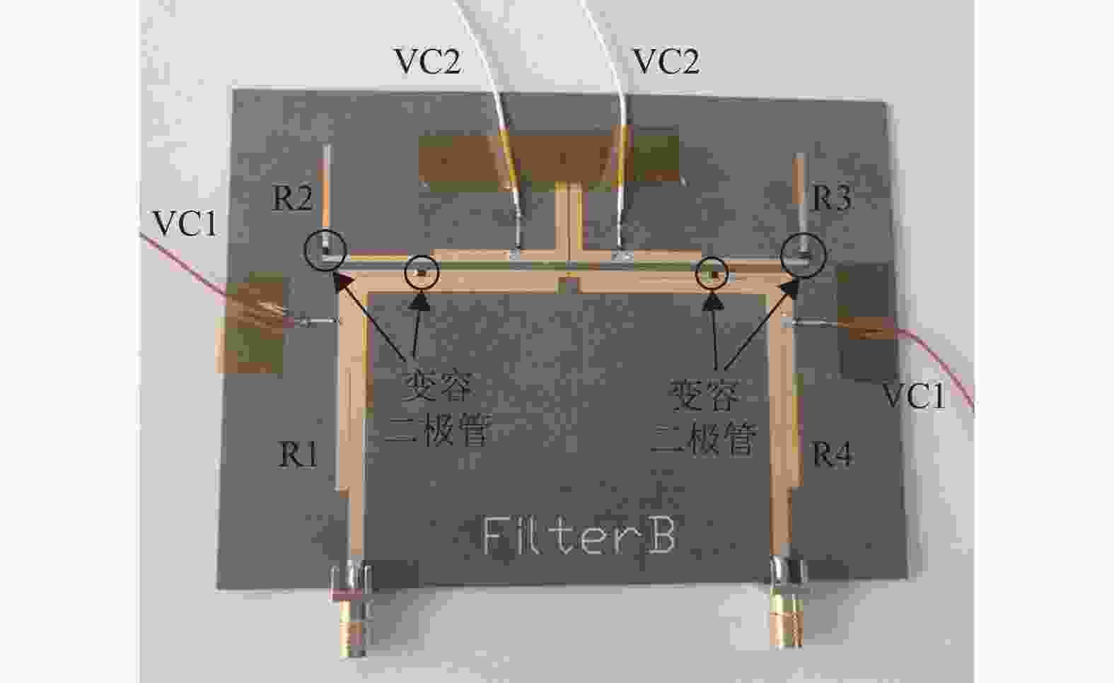
图 11 滤波器实物图
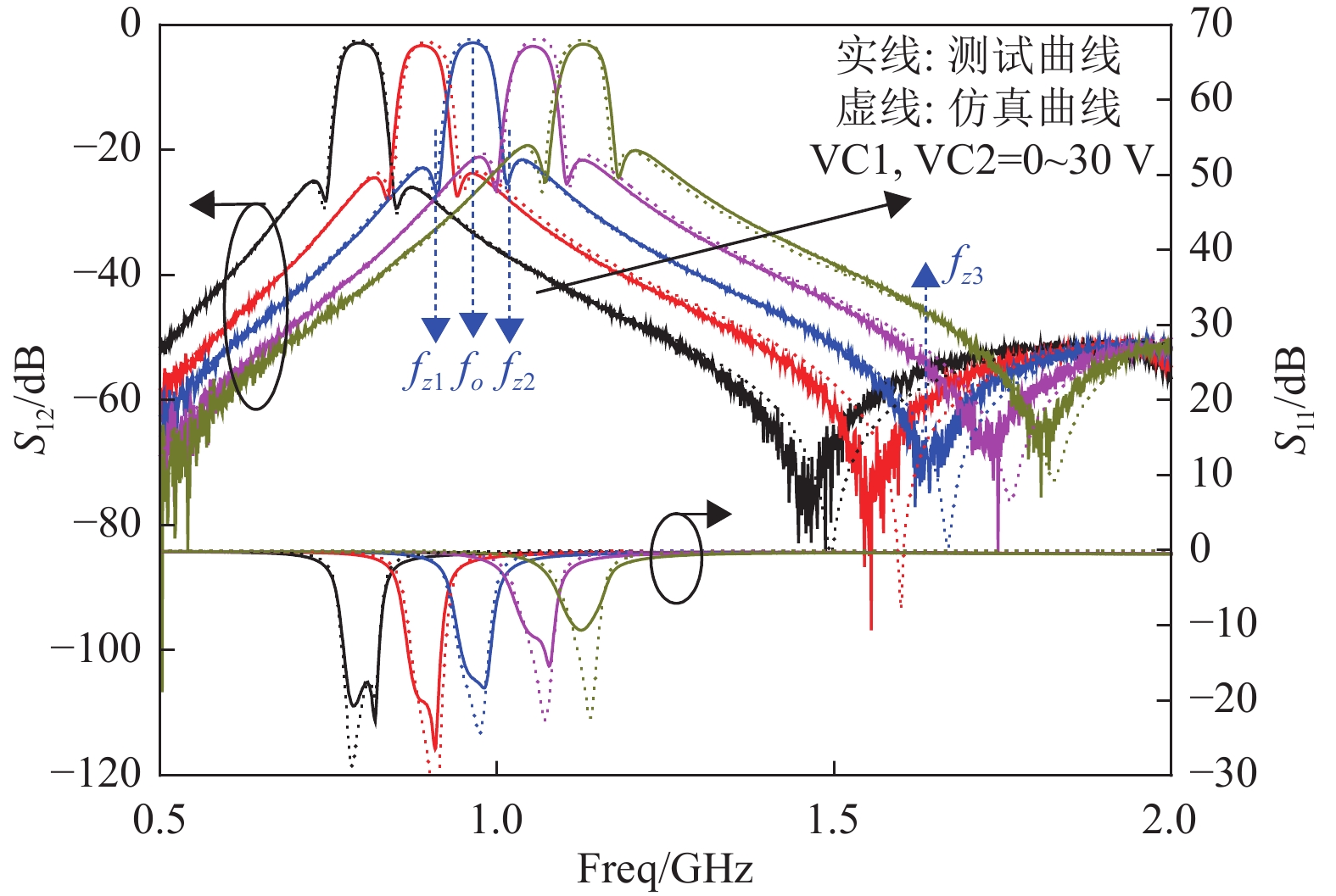
使用Keysight公司的N5244A型号矢量网络分析仪对加工的滤波器进行测试,仿真和测试的频率响应如图12所示,测试结果和仿真结果吻合良好,两者存在的偏差主要由加工误差导致。图12中5条曲线中心频率分别为0.79 GHz,0.89 GHz,0.96 GHz,1.06 GHz,1.14 GHz,对应的偏置电压VC1/VC2分别为0/0 V,2.1/2.2 V,6.5/6.6 V,13.4/14.2 V,27.2/30 V。结果表明,滤波器中心频率可以在0.79 ~ 1.14GHz之间连续调谐,滤波器调谐率约为36.2%。在整个调谐范围内,滤波器的回波损耗优于10 dB,插入损耗为2.8~3.3 dB。同时,在频率调谐过程中,该滤波器3 dB绝对带宽保持在55±3 MHz,实现了恒定的恒定绝对带宽特性。滤波器在通带近端产生两个传输零点,有效提高了滤波器的选择性,另外在通带远端产生了另外两个传输零点,改善了阻带性能。以下图中蓝色曲线为例对滤波器零点分布进行说明。下图蓝色曲线S21的中心频率fo为0.963 GHz,三个传输零点fz1=0.915 GHz,fz2=1.013 GHz和fz3=1.713 GHz,3 dB绝对带宽为55 MHz。因此,fz1、fz2、fz3的归一化频率分别为−1.79、1.77、21.3。fz3的归一化频率大于20,因为源和负载的实际耦合可能小于0.0006,由于测量仪器的量程限制,通带远端左侧的传输零点在图12中未显示。
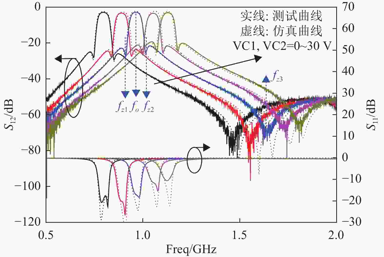
图 12 滤波器仿真和测试结果
表1给出了本文所设计的频率可调滤波器与一些之前相似工作典型性能的比较。由下表可以看出,与其他一些基于均匀阻抗谐振器和双模谐振器的可调滤波器相比,本文所提出基于VL-SIR的可调滤波器实现了更宽的调谐范围。同时,该滤波器通过引入交叉耦合,实现了四传输零点的特性,滤波器的选择性和阻带性能都得到了改善。此外,在滤波器频率调谐过程中,滤波器的绝对带宽可以保持稳定,这一特性在一些实际应用中非常有用。
表 1 滤波器典型性能对比
参考文献 频率/GHZ 调谐率/% 带宽/MHZ 插损/dB 阶数 零点个数 谐振器 恒定绝对带宽 尺寸(λg×λg) [10] 1.5-1.8 18.1 119 2.5 2 0 UIR YES 0.18x0.13 [13] 0.57-0.79 32 51 4.1 2 2 UIR YES 0.1 x 0.1 [18] 2.5-3 21 630 1.1 3 2 DMR NO NG [24] 1.21-1.58 26.8 133 3 4 4 UIR YES 0.73 x 0.11 [25] 0.89-1.13 23.8 46.8 4.3 4 2 UIR YES 0.23 x 0.19 Proposed 0.79-1.14 36.2 55 3.3 4 4 VL-SIR YES 0.16 x 0.25 备注: NG: 未给出; DMR: 双模谐振器。 -
本文提出一种基于VL-SIR的4阶4零点频率可调带通滤波器设计,该滤波器首次将变容二极管加载的阶跃阻抗谐振器用于4阶可调滤波器设计,相较于传统均匀阻抗谐振器,滤波器实现了更宽的调谐范围和紧凑的尺寸。同时,该滤波器采用CQ拓扑结构,在谐振器R1/R4之间引入交叉耦合,在通带近端产生一对传输零点,改善了滤波器的选择性。引入源和负载端的耦合,在通带远端产生另一对传输零点,改善了滤波器的阻带性能。此外,谐振器之间和馈电部分采用频变耦合结构,使得可调滤波器的绝对带宽在整个调谐范围内保持稳定。所提出的频率可调滤波器实现了良好的综合性能,在可重构射频前端设计中具有良好的应用前景。
Design of fourth-order frequency tunable bandpass filter using varactor-loaded step-impedance resonators
-
摘要: 本文提出一种基于阶跃阻抗谐振器的紧凑型四阶四零点频率可调滤波器设计。滤波器使用变容二极管加载的阶跃阻抗谐振器(VL-SIR),有效拓宽了滤波器的调谐范围。在VL -SIR之间引入交叉耦合,从而在滤波器通带近端产生一对传输零点,显著提高了滤波器的选择性。同时,引入源和负载端的交叉耦合,在通带远端生成一对传输零点,以提高带外抑制。此外,采用基于VL-SIR的频变耦合结构来实现恒定绝对带宽。仿真结果与实测结果吻合良好。测量结果显示,可调滤波器频率调谐范围为0.78至1.15 GHz,3 dB绝对带宽约为55±3 MHz,滤波器的回波损耗大于10 dB,插入损耗约为2.8~3.3 dB。
-
关键词:
- 带通滤波器 /
- 微带 /
- 可调滤波器 /
- 变容管加载的阶跃阻抗谐振器
Abstract: In this article, a compact fourth-order frequency tunable bandpass filter (BPF) with four Transmission Zeros (TZs) based on Varactor-Loaded Step-Impedance Resonators (VL-SIRs) is presented. With the utilization of VL-SIRs, the Tuning Range (TR) of the proposed fourth-order BPF is improved. Besides, by introducing cross coupling between VL-SIRs, a pair of TZs close to the passband are produced and the selectivity of the filter is enhanced significantly. Another pair of TZs are generated to improve the out-of-band rejection by using source-load coupling. Moreover, the Frequency-Dependent Coupling (FDC) structures based on VL-SIRs are employed to realize constant Absolute Bandwidth (ABW). The simulated and measured results are presented and show good agreement. The measured results exhibit a tuning range from 0.78 GHz to 1.15 GHz with a 3-dB constant ABW of about 55±3 MHz, the return loss of the filter is greater than 10 dB and the insertion loss is about 2.8 dB to 3.3 dB.-
Key words:
- Bandpass filter /
- microstip /
- tunable filter /
- varactor-loaded step impedance resonator
-
表 1 滤波器典型性能对比
参考文献 频率/GHZ 调谐率/% 带宽/MHZ 插损/dB 阶数 零点个数 谐振器 恒定绝对带宽 尺寸(λg×λg) [10] 1.5-1.8 18.1 119 2.5 2 0 UIR YES 0.18x0.13 [13] 0.57-0.79 32 51 4.1 2 2 UIR YES 0.1 x 0.1 [18] 2.5-3 21 630 1.1 3 2 DMR NO NG [24] 1.21-1.58 26.8 133 3 4 4 UIR YES 0.73 x 0.11 [25] 0.89-1.13 23.8 46.8 4.3 4 2 UIR YES 0.23 x 0.19 Proposed 0.79-1.14 36.2 55 3.3 4 4 VL-SIR YES 0.16 x 0.25 备注: NG: 未给出; DMR: 双模谐振器。  下载: 导出CSV
-
[1] DOUMANIS E, GOUSSETIS G, VUORIO J, et al. Tunable filters for Agile 5G new radio base transceiver stations[J]. IEEE Microwave Magazine, 2021, 22(11): 26-37. doi: 10.1109/MMM.2021.3102200 [2] AL-YASIR Y, OJAROUDI P N, ABD-ALHAMEED R, et al. Recent progress in the design of 4G/5G reconfigurable filters[J]. Electronics, 2019, 8(1): 114. doi: 10.3390/electronics8010114 [3] 李双, 李胜先, 史曼. 可重构微波滤波器研究现状及发展趋势[J]. 无线电工程, 2023, 53(6): 1390-1402. doi: 10.3969/j.issn.1003-3106.2023.06.019 LI S, LI S X, SHI M. Recent research and trends in the design of reconfigurable filters[J]. Radio Engineering, 2023, 53(6): 1390-1402. doi: 10.3969/j.issn.1003-3106.2023.06.019 [4] ISLAM H, DAS S, BOSE T, et al. Diode based reconfigurable microwave filters for cognitive radio applications: A review[J]. IEEE Access, 2020, 8: 185429-185444. doi: 10.1109/ACCESS.2020.3030020 [5] GUYETTE A C. Intrinsically switched varactor-tuned filters and filter banks[J]. IEEE Transactions on Microwave Theory and Techniques, 2012, 60(4): 1044-1056. doi: 10.1109/TMTT.2012.2184131 [6] CHENG F, LIN X Q, HU Y Y, et al. Tunable bandpass filter using varactor-loaded quarter-wavelength resonator[C]//Proceedings of the International Conference on Microwave and Millimeter Wave Technology. New York: IEEE, 2012. [7] GE C, ZHU X W. Highly-selective tunable bandpass filter with two-path mixed coupling[J]. IEEE Microwave and Wireless Components Letters, 2014, 24(7): 451-453. doi: 10.1109/LMWC.2014.2316218 [8] HUANG X G, FENG Q Y, ZHU L, et al. Synthesis and design of tunable bandpass filters with constant absolute bandwidth using varactor-loaded microstrip resonator[J]. International Journal of RF and Microwave Computer-Aided Engineering, 2014, 24(6): 681-689. doi: 10.1002/mmce.20812 [9] ZHOU W J, CHEN J X. High-selectivity tunable balanced bandpass filter with constant absolute bandwidth[J]. IEEE Transactions on Circuits and Systems II:Express Briefs, 2017, 64(8): 917-921. [10] KUMAR N, NARAYANA S, SINGH Y K. Constant absolute bandwidth tunable symmetric and asymmetric bandpass responses based on reconfigurable transmission zeros and bandwidth[J]. IEEE Transactions on Circuits and Systems II:Express Briefs, 2022, 69(3): 1014-1018. [11] CHI P L, YANG T, TSAI T Y. A fully tunable two-pole bandpass filter[J]. IEEE Microwave and Wireless Components Letters, 2015, 25(5): 292-294. doi: 10.1109/LMWC.2015.2409794 [12] LIN F, RAIS-ZADEH M. Continuously tunable 0.55–1.9-GHz bandpass filter with a constant bandwidth using switchable varactor-tuned resonators[J]. IEEE Transactions on Microwave Theory and Techniques, 2017, 65(3): 792-803. doi: 10.1109/TMTT.2016.2633270 [13] ZHANG Y J, CAI J, CHEN J X. Design of novel reconfigurable filter with simultaneously tunable and switchable passband[J]. IEEE Access, 2019, 7: 59708-59715. [LinkOut] [14] YOU B, CHEN L, LIANG Y P, et al. A high-selectivity tunable dual-band bandpass filter using stub-loaded stepped-impedance resonators[J]. IEEE Microwave and Wireless Components Letters, 2014, 24(11): 736-738. doi: 10.1109/LMWC.2014.2348322 [15] QIN W, CAI J, LI Y L, et al. Wideband tunable bandpass filter using optimized varactor-loaded SIRs[J]. IEEE Microwave and Wireless Components Letters, 2017, 27(9): 812-814. doi: 10.1109/LMWC.2017.2734848 [16] CHEN J X, ZHANG Y J, CAI J, et al. Overall study of frequency-agile mechanism of varactor-loaded λ/4 resonator for designing tunable filter with stable wide stopband[J]. IEEE Transactions on Industrial Electronics, 2019, 66(8): 6302-6310. [LinkOut] [17] DENG H W, SUN L, LIU F, et al. Compact tunable balanced bandpass filter with constant bandwidth based on magnetically coupled resonators[J]. IEEE Microwave and Wireless Components Letters, 2019, 29(4): 264-266. [LinkOut] [18] CHEN Z H, CHU Q X. Wideband fully tunable bandpass filter based on flexibly multi-mode tuning[J]. IEEE Microwave and Wireless Components Letters, 2016, 26(10): 789-791. [LinkOut] [19] GAO L, LIN T W, REBEIZ G M. Design of tunable multi-pole multi-zero bandpass filters and diplexer with high selectivity and isolation[J]. IEEE Transactions on Circuits and Systems I: Regular Papers, 2019, 66(10): 3831-3842. [LinkOut] [20] LU D, TANG X H, BARKER N S, et al. Single-band and switchable dual-/ single-band tunable BPFs with predefined tuning range, bandwidth, and selectivity[J]. IEEE Transactions on Microwave Theory and Techniques, 2018, 66(3): 1215-1227. [LinkOut] [21] ABDELFATTAH M, ZHANG R Q, PEROULIS D. High-selectivity tunable filters with dual-mode SIW resonators in an L-shaped coupling scheme[J]. IEEE Transactions on Microwave Theory and Techniques, 2019, 67(12): 5016-5028. [LinkOut] [22] GAO L, REBEIZ G M. A 0.97–1.53-GHz tunable four-pole bandpass filter with four transmission zeroes[J]. IEEE Microwave and Wireless Components Letters, 2019, 29(3): 195-197. [LinkOut] [23] TIAN D Y, FENG Q Y, XIANG Q Y. Synthesis applied 4th-order constant absolute bandwidth frequency-agile bandpass filter with cross-coupling[J]. IEEE Access, 2018, 6: 72287-72294. [LinkOut] [24] LU D, YU M, BARKER N S, et al. Advanced synthesis of wide-tuning-range frequency-adaptive bandpass filter with constant absolute bandwidth[J]. IEEE Transactions on Microwave Theory and Techniques, 2019, 67(11): 4362-4375. [LinkOut] [25] OHIRA M, HASHIMOTO S, MA Z W, et al. Coupling-matrix-based systematic design of single-DC-bias-controlled microstrip higher order tunable bandpass filters with constant absolute bandwidth and transmission zeros[J]. IEEE Transactions on Microwave Theory and Techniques, 2019, 67(1): 118-128. [LinkOut] [26] TIAN D, FENG Q, XIANG Q. Design of high order cross-coupled constant absolute bandwidth frequency-agile bandpass filters[J]. Applied Computational Electromagnetics Society journal, 2019, 34(9): 1373. [27] HONG J S, LANCASTER M J. Microstrip Filters for RF/Microwave Applications[M]. ■■: Wiley, 2001. [28] CAMERON R J, KUDSIA C M, MANSOUR R R. Microwave Filters for Communication Systems: Fundamentals, Design and Applications[M]. 2ed. Hoboken, USA: Wiley, 2018. [29] TANG C W, TSENG C T, CHANG S C. Design of the compact tunable filter with modified coupled lines[J]. IEEE Transactions on Components, Packaging and Manufacturing Technology, 2014, 4(11): 1815-1821. doi: 10.1109/TCPMT.2014.2349151 [30] CAI J, CHEN J X, ZHANG X F, et al. Electrically varactor-tuned bandpass filter with constant bandwidth and self-adaptive transmission zeros[J]. IET Microwaves, Antennas & Propagation, 2017, 11(11): 1542-1548. -

 点击查看大图
图(12) / 表(1)
计量
- 文章访问数: 283
- HTML全文浏览量: 92
- PDF下载量: 2
- 被引次数: 0