ISSN
ISSN 


-
Array factor (AF) theory is always used to estimate the performances of the antenna array[1]. For a specified beam direction, the phase distribution of each element can be calculated by the AF theory easily. It works well for the large antenna array with actual antenna element using this phase distribution, which is attributable to the same coupling environments of array elements. However, there is a discrepancy between the actual beam direction and desired direction for the small antenna array due to the mutual coupling, which will make the radiation pattern of each element in the antenna array to be totally different.
With the active element pattern (AEP) method[2-5], the mutual coupling is considered, thus the far field pattern of antenna array can be calculated by the superposition of AEP. This assertion is verified by the numerical simulation, which means the radiation pattern of antenna array can be obtained with this method efficiently.
The excitation including amplitude and phase for each element should be optimized to make the antenna array satisfy specified requirements such as beam steering and low side-lobe. Some analytical methods have been proposed[1]. However, it only can be used for the simple array configuration. Also, effects of the actual antenna element and mutual coupling are not considered at all. To tackle these deficiencies, a proper remedy must be developed. Globally optimized methods such as the genetic algorithm (GA) and particle swarm optimization (PSO) are proposed to address these issues[6-7]. GA is complicated to implement because it involves operations including the selection, crossover, and mutation. Though PSO did not suffers this problem, convergence of the PSO algorithm depends on the choice of boundary conditions and the maximum velocity. As we know, they are difficult to perceive, so it always makes the PSO be trapped in local minima.
Invasive weed optimization (IWO)[8] method proposed by Mehrabian and Lucus in 2006, has been applied to antenna community for the synthesis of antenna array and antenna design[9-11]. It is found that IWO outperforms GA and PSO. In addition, IWO has the features of easy implementation and skipped local minima. Therefore, issues discussed above can be handled by IWO.
In this paper, the phase distribution of small antenna array is optimized by the hybrid IWO-AEP. Since the mutual coupling is considered in AEP, the beam peak can steer to the desired direction accurately. Simultaneously, because the digital phase shifter is always employed to feed the antenna, the quantization errors are discussed either. It has little effect on the antenna performance, so the proposed antenna also has the feature of stability.
-
AEP defines the radiation pattern of the array when one radiating element is driven and all the others are terminated with matching load[3]. Because the mutual coupling is included in the AEP, far field pattern of the entire antenna array can be obtained accurately by the superstition of AEP. The total electric field can be expressed:
$$ {{\mathit{\boldsymbol{E}}}_{T}}(\theta ,\varphi )=\sum\limits_{n=1}^{N}{{{\mathit{\boldsymbol{I}}}_{n}}}\times {{\mathit{\boldsymbol{E}}}_{n}}(\theta ,\varphi ) $$ (1) where ${{\mathit{\boldsymbol{E}}}_{T}}(\theta ,\varphi )$ defines the total electric field radiated by the array, ${{\mathit{\boldsymbol{I}}}_{n}}$ represents the excited current for the n-th element, ${{\mathit{\boldsymbol{E}}}_{n}}(\theta ,\varphi )$ denotes the electric field radiated by the n-th element, and N is the total elements number of the array.
-
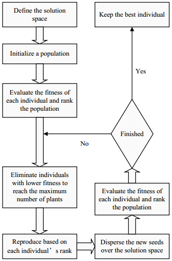
Because IWO has been intensively studied in Ref. [8], only main steps of IWO are given in this paper. Namely,
① Population initialization
② Reproduction
③ Spatial dispersal
④ Competitive exclusion.
The flowchart of IWO is shown in Fig. 1. Details of IWO and its application in electromagnetics community can be found in Refs. [8-9].

Figure 1. Flowchart of IWO
-
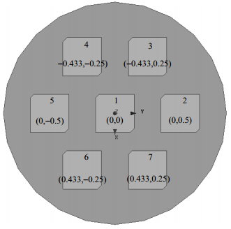
Configuration of antenna array is shown in Fig. 2. It consists of 7 conventional circularly polarized microstrip antennas and all of them are distributed with the circular ring configuration. Position of each element is also shown in Fig. 2 and the interspaces between elements are half wavelength.

Figure 2. Configuration of the small antenna array
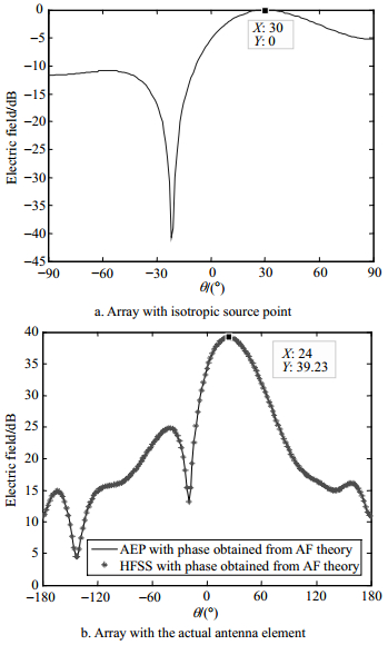
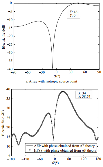
To make this antenna array steer to a desired direction, each element should be fed with a given phase distribution. If the theory of AF is applied to calculate the phase distribution, as shown in Fig. 3 and Fig. 4, there will be discrepancy for the beam direction when the actual antenna element is considered. The beam peak steers to 24° when the presumed one is 30°, while it steers to 34° when the presumed one is 46°. The discrepancy is caused by the mutual coupling, which will make the radiation pattern of each element in the array to be totally different.

Figure 3. Radiation pattern (presume to steer to 30°) of antenna array with the phase distribution of AF theory

Figure 4. Radiation pattern (presume to steer to 46°) of antenna array with the phase distribution of AF theory
To overcome this problem, IWO is combined with AEP to optimize the phase distribution of the antenna array. Firstly, the radiation pattern of the antenna array is synthesized with the AEP. Then, IWO is used to optimize the phase excitation of each element. With this hybrid method, the antenna array can steer to the desired direction accurately and efficiently, since the mutual coupling is considered in AEP and it avoids the full wave simulation. The fitness function of IWO is defined as:
$$ f=0.7\times \text{abs}(\theta -{{\theta }_{d}})+0.3\times \text{abs}(G-{{G}_{d}}) $$ (2) where ${{\theta }_{d}}$ defines the desired beam direction and ${{G}_{d}}$ denotes the desired gain.
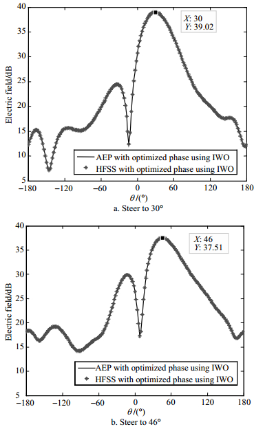
Parameters used in IWO are shown in table 1. After running the IWO, the optimized phase distribution is listed in Table 2 and Table 3. The radiation pattern with the optimized phase distribution is presented in Fig. 5. It is noted that the beam peak can steer to the desired direction accurately.
Table 1. Parameters used in the IWO
Number of initial population
(n_ini)Maximum number of iterations
(Iter_max)Maximum number of plants
(P_max)Maximum number of seeds
(S_max)30 300 30 5 Minimum number of seeds
(S_min)Nonlinear modulation index
(N)Initial value of standard deviation
(SD_initial)Final value of standard deviation
(SD_final)0 3 8 0.1 Table 2. Phase distribution for beam steering to (90°, 30°)
Element number AF theory Phase/(°) Optimized using IWO Continuous Digital (5 bit) 1 0 168.1 168.75 2 −90 63.7 67.5 3 −45 120.1 123.75 4 45 −141 −146.25 5 90 −70.7 −67.5 6 45 −130.2 −135 7 −45 118.5 123.75 Table 3. Phase distribution for beam steering to (90°, 46°)
Element number AF theory Phase/(°) Optimized using IWO Continuous Digital (5 bit) 1 0 −1.9 0 2 −129.5 177.1 180 3 −64.7 −84.4 −90 4 64.7 88.4 90 5 129.5 178.1 180 6 64.7 76.8 78.75 7 −64.7 −101.4 −101.25 
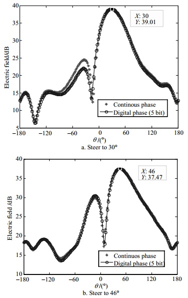
Figure 5. Radiation pattern of antenna array with the optimized phase distribution
For the engineering application, the digital phase shifter is always used to feed the antenna array, so the quantization error should be estimated. After discretizing the optimized phase with 5 bit phase shifter, as shown in Table 2 and Table 3, the simulated radiation pattern is shown in Fig. 6. It is observed that the quantization error has trivial effect on the antenna performances and the radiation pattern is almost remained with the digital phase distribution, which also demonstrates the stability of the proposed hybrid method.

Figure 6. Radiation pattern of antenna array with digital phase shifter
-
A small antenna array with 7 elements is designed to verify the proposed hybrid method. With the proposed hybrid method, beam direction of the array can precisely steer to the desired direction. The results obtained from the proposed method are compared with those from the commercial full wave solver software HFSS, and good agreements are achieved between them. Since the full wave simulation is avoided, the proposed hybrid method also has the advantage of high efficiency. Quantization error is also considered for the engineering application, which demonstrates the stability of the proposed method. In addition, the proposed method can be used for the arbitrary array configuration.
-
摘要: 基于有源方向图叠加原理和杂草入侵优化算法对小规模天线阵列的波束指向进行了校准。对于小规模阵列,由于天线单元之间的互耦导致阵中每个单元的方向图各不相同,如果使用阵因子理论对其配相,阵列无法扫描到期望的波束指向。为了考虑互耦的的影响,利用有源方向图叠加原理合成整个阵列的方向图;再将杂草入侵优化算法和有源方向图叠加原理进行结合对每个单元的馈电相位进行优化。基于该混合算法,对一个7元平面阵列进行了优化,优化后的相位分布可以使该阵列扫描到期望的波束指向,解决了小规模阵列的波束指向偏差问题。Abstract: A hybrid method that combines the theory of superstition of active element pattern (AEP) and invasive weed optimization (IWO) is proposed for calibrating the beam direction of small antenna arrays. For a small antenna array with only a few elements, the beam direction discrepancy of each element will arise due to the mutual coupling of antenna elements if the array is fed with phase distribution based on the array factor (AF) theory. In this paper, the mutual coupling effects among elements in a small antenna array are considered. AEP method is employed to synthesize the radiation pattern of the antenna array. The phase distribution is optimized by the IWO. With the proposed hybrid method, the beam peak of the small antenna array can accurately steer to the desired direction.
-
Figure 3. Radiation pattern (presume to steer to 30°) of antenna array with the phase distribution of AF theory
Figure 4. Radiation pattern (presume to steer to 46°) of antenna array with the phase distribution of AF theory
Table 1. Parameters used in the IWO
Number of initial population
(n_ini)Maximum number of iterations
(Iter_max)Maximum number of plants
(P_max)Maximum number of seeds
(S_max)30 300 30 5 Minimum number of seeds
(S_min)Nonlinear modulation index
(N)Initial value of standard deviation
(SD_initial)Final value of standard deviation
(SD_final)0 3 8 0.1  下载: 导出CSV
Table 2. Phase distribution for beam steering to (90°, 30°)
Element number AF theory Phase/(°) Optimized using IWO Continuous Digital (5 bit) 1 0 168.1 168.75 2 −90 63.7 67.5 3 −45 120.1 123.75 4 45 −141 −146.25 5 90 −70.7 −67.5 6 45 −130.2 −135 7 −45 118.5 123.75
下载: 导出CSV
Table 3. Phase distribution for beam steering to (90°, 46°)
Element number AF theory Phase/(°) Optimized using IWO Continuous Digital (5 bit) 1 0 −1.9 0 2 −129.5 177.1 180 3 −64.7 −84.4 −90 4 64.7 88.4 90 5 129.5 178.1 180 6 64.7 76.8 78.75 7 −64.7 −101.4 −101.25
下载: 导出CSV
-
[1] BALANIS C A. Antenna theory: Analysis and design[M]. 3rd ed. New Jersey, USA: John Wiley & Sons Inc, 2005. [2] POZAR D M. The active element pattern[J]. IEEE Transactions on Antennas and Propagation, 1994, 42(8):1176-1178. doi: 10.1109/8.310010 [3] ZHANG Shuai, GONG Shu-xi, GONG Qi, et al. Application of the active element pattern method for calculation of the scattering pattern[J]. IEEE Antennas and Wireless Propagation Letters, 2011, 10:83-86. doi: 10.1109/LAWP.2011.2111410 [4] HE Qing-qiang, WANG Bing-zhong, SHAO Wei. Radiation pattern calculation for arbitrary conformal arrays that include mutual-coupling effect[J]. IEEE Antennas and Propagation Magazine, 2010, 52(2):57-63. doi: 10.1109/MAP.2010.5525566 [5] OUYANG Jun, LUO Xuan, YANG Jie, et al. Analysis and synthesis of conformal conical surface linear phased array with volume surface integral equation+AEP (active Element Pattern) and INSGA-Ⅱ[J]. IET Microwaves, Antennas & Propagation, 2012, 6(11):1277-1285. [6] ALLARD R J, WERNER D H, WERNER P J L. Radiation pattern synthesis for arrays of conformal antennas mounted on arbitrarily-shaped three-Dimensional platforms using genetic algorithms[J]. IEEE Transactions on Antennas and Propagation, 2003, 51(5):1054-1062. doi: 10.1109/TAP.2003.811510 [7] LI Wen-tao, SHI Xiao-wei, HEI Yong-qiang, et al. A hybrid optimization algorithm and its application for conformal array pattern synthesis[J]. IEEE Transactions on Antennas and Propagation, 2010, 58(10):3401-3406. doi: 10.1109/TAP.2010.2050425 [8] MEHRABIAN A R, LUCAS C. A novel numerical optimization algorithm inspired from weed colonization[J]. Ecological Informatics, 2006, 1(4):355-366. doi: 10.1016/j.ecoinf.2006.07.003 [9] KARIMKASHI S, KISHK A A. Invasive weed optimization and its features in electromagnetic[J]. IEEE Transactions on Antennas and Propagation, 2010, 58(4):1269-1278. doi: 10.1109/TAP.2010.2041163 [10] LI Yan, YANG Feng, OUYANG Jun, et al. Yagi-uda antenna optimization based on invasive weed optimization method[J]. Electromagnetics, 2011, 31(8):571-577. doi: 10.1080/02726343.2011.621108 [11] MOHAMADI M F, KOMJANI N, MOUSAVI P. Application of invasive weed optimization to design a broadband patch antenna with symmetric radiation pattern[J]. IEEE Antennas and Wireless Propagation Letters, 2011, 10:1369-1372. doi: 10.1109/LAWP.2011.2177801 -

 点击查看大图
图(6) / 表(3)
计量
- 文章访问数: 3623
- HTML全文浏览量: 1126
- PDF下载量: 149
- 被引次数: 0