ISSN
ISSN 


 下载:
下载:


-
Alternating current plasma display panel (AC PDP) has many advantages, such as high brightness, good color rendition, rich gray scale, fast response speed of moving picture, strong electric and magnetic immunity, and thin thickness[1-4]. Until the beginning of this century, AC PDP has been considered to be one of the most promising alternatives to the traditional cathode ray tubes. However, the market share of AC PDP in the commercial FPD market is declining now. The most fundamental reason is attributed to its low power efficiency and high cost. To reduce the power consumption, researches on discharge gas components, discharge cell structure, and driving circuit have been done. Furthermore, many studies on the performance improvement of the protecting layer of AC PDP have emerged recently. One of the methods is to dope impurities into MgO, such as Na-doped MgO[5], Si-doped MgO[6], Ca-doped MgO[7], and Zn-doped MgO[8]. Another method is to coat some films or nanoparticles on MgO film, such as LaB6/MgO[1], SrO/MgO[9], Au nanoparticles/MgO[10], MgO nanoparticles/MgO[11], Mg particles/ MgO[12], and MgCaO/Li-doped MgO[13].
In this paper, Zn- and Sn-doped MgO powder was prepared by a chemical coprecipitation process. Then the Zn- and Sn-doped MgO powder was formulated into slurry and coated on MgO protective layer by the spin coating technology. The structure, appearance, and visible light transmission of Zn- and Sn-doped MgO powdered functional layer on the surface of AC PDP front panel were studied. The discharge voltages of Zn- and Sn-doped MgO functional layers measurement confirmed that the Zn- and Sn-doped MgO particle leaded to a notable improvement of power efficiency of AC PDP.
-
Metal precursor solution of fabricating Zn- and Sn-doped MgO powder was prepared by dissolving 5.0×10⁻⁴ mol zinc acetate dihydrate [Zn(CH3COO)2·2H2O], 2.5×10⁻⁴ mol tin (Ⅱ) chloride [SnCl2·2H2O], and 0.025 mol magnesium nitrate hydrate [Mg(NO3)2·6H2O] in absolute ethyl alcohol (100 mL). Then 4 mL ethanol amine and 16 mL polyethylene glycol (PEG 400) were mixed and added to the above solution. Subsequently, 20 mL absolute ethyl alcohol and 20 mL ammonia were mixed and added dropwise to the metal ion solution at 70 ℃, followed by constant magnetic stirring for 2 h and standing for 8 h. The obtained precipitate was washed with ethanol and deionized water repeatedly several times, and annealed at high temperature for 4 h. Next, the powder was mixed with PEG-400 and ethanol in a mass ratio of 1:1:10 and this slurry was spin coated onto AC PDP front panel with speed of 100 r/min.
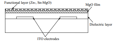
The schematic diagram of the panel with functional layer was shown in Fig. 1 and specific parameters were reported in our previous work[14]. XRD and XPS were used to analyze the structure of the functional layer. Moreover, in order to study the effect of functional layers on the morphology and transmittance of AC PDP, SEM and an ultraviolet -visible spectrophotometer were introduced, respectively.

Figure 1. Structure of AC PDP front panel with Zn- and Sn-doped MgO powdered functional layer.
-
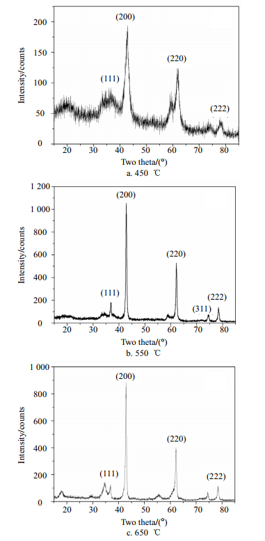
The XRD patterns of the Zn- and Sn-doped MgO powder annealed at different temperatures are shown in Fig. 2a~Fig. 2c. At 450 ℃ (Fig. 2a), each orientation peak of MgO was low, indicating the poor crystallinity. At 550 ℃ (Fig. 2a), the sample had excellent crystallinity and no feature peaks from zincite or tin oxide were observed. The (200) orientation of MgO presents the strongest intensity. When the annealing temperature was up to 650 ℃, (200), (220) and (222) orientation peaks of MgO decreased and some impurity peaks appeared. Thus, 550 ℃ was accepted as our final annealing temperature. The possible reactions existing in this experiment were discussed as follows. First, ammonia hydrolyzed and released OH-. In the alkaline conditions, Zn(CH3COO)2·2H2O, SnCl2·2H2O and Mg(NO3)2·6H2O hydrolyzed, respectively, i.e.
$$ {\rm{Zn(C}}{{\rm{H}}_{\rm{3}}}{\rm{COO}}{{\rm{)}}_{\rm{2}}}{\rm{\cdot2}}{{\rm{H}}_{\rm{2}}}{\rm{O}} \to {\rm{Zn}}{\left( {{\rm{OH}}} \right)_{\rm{2}}}{\rm{ + 2C}}{{\rm{H}}_{\rm{3}}}{\rm{COOH}} \uparrow $$ (1) $$ {\rm{SnC}}{{\rm{l}}_{\rm{2}}}{\rm{\cdot2}}{{\rm{H}}_{\rm{2}}}{\rm{O}} \to {\rm{Sn}}{\left( {{\rm{OH}}} \right)_{\rm{2}}}{\rm{ + 2HCl}} \uparrow $$ (2) $$ {\rm{Mg(N}}{{\rm{O}}_{\rm{3}}}{{\rm{)}}_{\rm{2}}}{\rm{\cdot6}}{{\rm{H}}_{\rm{2}}}{\rm{O}} \to {\rm{Mg}}{\left( {{\rm{OH}}} \right)_{\rm{2}}}{\rm{ + 2HN}}{{\rm{O}}_3} \uparrow {\rm{ + 4}}{{\rm{H}}_{\rm{2}}}{\rm{O}} $$ (3) 
Figure 2. XRD patterns of Zn- and Sn-doped MgO powder as a function of annealing temperature
Then, Zn(OH)2, Sn(OH)2 and Mg(OH)2 decomposed in the annealing furnace and the corresponding reaction were:
$$ \begin{array}{l} x{\rm{Zn}}{\left( {{\rm{OH}}} \right)_2} + y{\rm{Sn}}{\left( {{\rm{OH}}} \right)_2} + z{\rm{Mg}}{\left( {{\rm{OH}}} \right)_2} \to \\ \;\;\;{\rm{Z}}{{\rm{n}}_x}{\rm{S}}{{\rm{n}}_y}{\rm{M}}{{\rm{g}}_z}{{\rm{O}}_{\left( {x + y + z} \right)}} + \left( {x + y + z} \right){{\rm{H}}_{\rm{2}}}{\rm{O}} \end{array} $$ (4) According to the above reactions, the Zn- and Sn- doped MgO powder was fabricated successfully.
Fig. 3 shows the XPS pattern of fabricated Zn- and Sn-doped MgO powder. The Mg, Zn, Sn and O characteristic peaks could be clearly detected, which confirmed the existence of Zn and Sn element. Compared with the Mg and O feature peaks, the intensities of Zn and Sn peaks were relatively weak, which attributed to the less quantity of the dopant. The XRD and XPS results implied that Zn2+ and Sn2+ had been incorporated into the lattice of MgO. Moreover, it could be found that the diffraction angles of all diffraction peaks of the Zn- and Sn-doped MgO sample were nearly identical with pure MgO. The possible reason was that the doping amount of Zn and Sn in MgO was very small, although the ionic radius of Zn2+ and Sn2+ was larger than Mg2+ (Mg2+: 0.072 nm, Zn2+: 0.074 nm, Sn2+: 0.112 nm).

Figure 3. XPS pattern of Zn- and Sn-doped MgO powder
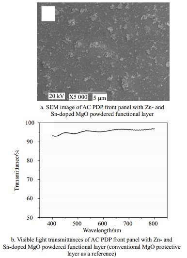
Fig. 4a shows the SEM image of the AC PDP front panel coated with Zn- and Sn-doped MgO powdered functional layer. The particles were evenly distributed on the substrate surface. Fig. 4b shows the visible light transmittances, in which the conventional AC PDP front panel without functional layer was used as a reference. Because of the favorable light transmittance of Zn- and Sn-doped MgO material and the discontinuous distribution of particle, the functional layer made the transmission only decreased by 4%~7% in the visible light wavelength, which was fit for application in AC PDP.

Figure 4. Effect of functional layers on the morphology and transmittance of AC PDP
Fig. 5 compares the firing and sustaining maximum voltages of AC PDP test panels with Zn- and Sn-doped MgO powdered functional layer and conventional MgO layer in 7% Xe-Ne. Within the gas pressure range of 200~450 torr, the panel with Zn- and Sn-doped MgO powdered functional layer always presented lower discharging voltage (firing and sustaining maximum voltages) than that with the conventional MgO layer.

Figure 5. Discharge characteristics of AC PDP test cells with Zn- and Sn- doped MgO powdered functional layer and pure MgO protective layer
For example, the firing and sustaining maximum voltages of Zn- and Sn-doped MgO powdered functional layer were 237 V and 249 V at 250 torr, which were about 17.1% and 18.4% lower than the pure MgO protective layer (286 V, 305 V), respectively. According to the Hagstrum theory[15], Auger neutralization is the main mechanism of secondary electrons emission in AC PDP, and valence electrons of the protective layer in AC PDP can be emitted to vacuum levels when the energy level meets the following condition[16]:
$$ E = E_{\text{i}}^0 - 2({E_{\text{g}}} + \chi ) > 0 $$ (5) where $E$, $E_{\text{i}}^0$, ${E_{\text{g}}}$, and $\chi $ are energy of emitted electron, the ionization energy of discharging gas atom, the band gap energy and the electron affinity of the protective layer. It is known that the band gap energy of MgO, ZnO and SnO2 are 7.8 eV, 3.37 eV and 3.6 eV, respectively. Thus, the protective layer coated Zn- and Sn-doped MgO powder is prone to produce more secondary electrons than pure MgO, which reduces the discharging voltages effectively.
-
In conclusion, Zn- and Sn-doped MgO powder has been prepared by a chemical coprecipitation method. It was spin coated on the commercial MgO protective layer in the AC PDP front panel. It was found that zinc and tin atoms were incorporated into the lattice of MgO, which was confirmed by XRD pattern and XPS spectra. The test panel with the Zn- and Sn-doped MgO powdered functional layer presented lower firing and sustain maximum voltages than the pure MgO protective layer did. With 250 torr 7% Xe-Ne pressure, the firing and sustain maximum voltages of the test panel with the Zn- and Sn-doped MgO functional layer were about 17.1% and 18.4% lower than that with a conventional MgO protective layer, respectively.
Effects of Zn- and Sn-Doped MgO Powdered Functional Layer on Discharge Characteristics in AC Plasma Display Panels
-
摘要: 采用化学共沉淀法制备出Zn/Sn共掺杂MgO纳米粉末,利用旋涂法将其涂覆在等离子体显示器(AC PDP)的前基板上作为功能层,以改善AC PDP的放电性能。X射线衍射(XRD)、光电子能谱(XPS)和扫描式电子显微镜(SEM)的分析结果表明,Zn和Sn原子被成功掺入MgO晶格中。紫外-可见分光光度计的测试结果显示,Zn/Sn共掺杂MgO功能层的加入使基板的可见光透过率降低了4%~7%。在200~450 torr、7% Xe+Ne的放电条件下,与传统AC PDP相比,新型功能层的加入有效降低了AC PDP的着火电压和维持电压。因此,该功能层对于提高AC PDP的放电效率和降低其功耗具有重要意义。Abstract: Zn- and Sn-doped MgO powder preparing via a chemical coprecipitation method was spin-coated on alternating current plasma display panel (AC PDP) front panel as a functional layer to improve the discharging performance of AC PDP. The new products were characterized by X-ray diffraction (XRD), X-ray photoelectrom spectroscopy (XPS), scanning electron microscope (SEM) and an ultraviolet-visible spectrophotometer. The results showed that zinc and tin atoms had been successfully incorporated into the crystal lattice of MgO, which made the transmission only decrease by 4%~7%. Within 7% Xe-Ne pressure range of 200~450 torr, the new functional layer consistently showed lower firing and sustain maximum voltages than that of the conventional MgO layer. Therefore, this functional layer was important for improving the discharge efficiency of AC PDP and reducing its power consumption.
-
Figure 1. Structure of AC PDP front panel with Zn- and Sn-doped MgO powdered functional layer.
Figure 2. XRD patterns of Zn- and Sn-doped MgO powder as a function of annealing temperature
-
[1] DENG J, ZENG B Q, WANG Y, et al. Fabrication and characteristics of LaB6-doped MgO protective layer for plasma display panels[J]. Materials Letters, 2014, 134:51-55. doi: 10.1016/j.matlet.2014.07.062 [2] PARK C S, JUNG E Y, KIM D H, et al. Experimental study on permanent image sticking of single and double barrier ribs in alternating-current plasma display panel[J]. Molecular Crystals Liquid Crystals, 2017, 645:112-122. doi: 10.1080/15421406.2016.1277491 [3] 邓江, 曾葆青. Al掺杂MgO保护层对二次电子发射系数的影响[J].电子科技大学学报, 2015, 44(3):375-380. doi: 10.3969/j.issn.1001-0548.2015.03.010 DENG Jiang, ZENG Bao-qing. Calculation of secondary electron emission coefficient of Al-doped MgO protective layer[J]. Journal of University of Electronic Science and Technology of China, 2015, 44(3):375-380. doi: 10.3969/j.issn.1001-0548.2015.03.010 [4] PARK C S, KIM D H, KIM J H, et al. Influence of overlapped sustain waveform on panel-aging characteristics based on MgO surface morphology variation in alternating-current plasma display panel[J]. Molecular Crystals Liquid Crystals, 2017, 645:72-80. http://manu50.magtech.com.cn/dzkjdx/CN/abstract/abstract32.shtml [5] AHN S I, LEE S E, RYU S H, et al. A study on the secondary electron emission from Na-ion-doped MgO films in relation to the discharge characteristics of plasma display panels[J]. Thin Solid Films, 2009, 517:1706-1709. doi: 10.1016/j.tsf.2008.08.176 [6] HA C H, KIM J K, WHANG K W. The operation characteristics of an alternating current plasma display panel with Si-doped MgO protecting layer[J]. IEEE Transactions on Electron Devices, 2008, 55:992-996. doi: 10.1109/TED.2008.917333 [7] LEE T H, CHEONG H W, KWON O, et al. Application of MgCaO cathode layer to plasma display panel for high luminous efficacy[J]. IEEE Transactions on Electron Devices, 2013, 60:301-304. doi: 10.1109/TED.2012.2224869 [8] AHN S G, YOON S H, KIM Y S. Secondary electron emission characteristics of MgO-ZnO alloy thin film layer for AC PDP[J]. Thin Solid Films, 2009, 517:4027-4030. doi: 10.1016/j.tsf.2009.01.184 [9] JUNG H Y, LEE T H, KWON O, et al. Realization of high luminous efficacy at low voltages in the plasma display panel with SrO-MgO double layer[J]. IEEE Electron Device Letter, 2010, 31:686-688. doi: 10.1109/LED.2010.2047236 [10] KIM W H, CHO K H, CHOI K C, et al. Influence of gold nanoparticles on the characteristics of plasma display panels[J]. IEEE Transactions on Electron Devices, 2010, 57:2644-2650. doi: 10.1109/TED.2010.2058850 [11] CHOI E H, SON C G, HAN Y G, et al. Discharge characteristics of MgO nano-powdered functional layer in AC-PDP[J]. Molecular Crystals Liquid Crystals, 2010, 531:401-407. http://www.wanfangdata.com.cn/details/detail.do?_type=perio&id=3d3dcc50ca64ca57c2ce7f8f2001b0c4 [12] PARK C S, PARSONS T, KIM D H, et al. Investigation for the effect of redeposited Mg particles on the discharge characteristics in an alternating-current plasma display panel[J]. Molecular Crystals Liquid Crystals, 2017, 645:65-71. doi: 10.1080/15421406.2016.1277474 [13] PARK C S, JUNG E Y, TAE H S. Improvement of luminous effciency using Li-doped MgO layer coated by MgCaO crystal powders in plasma display panels[J]. Molecular Crystals Liquid Crystals, 2017, 645:130-137. doi: 10.1080/15421406.2016.1277496 [14] 邓江, 王小菊.碳纳米管功能层在等离子体显示中的应用研究[J].电子科技大学学报, 2016, 45(1):151-154. http://manu50.magtech.com.cn/dzkjdx/CN/abstract/abstract198.shtml DENG Jiang, WANG Xiao-ju. Application of CNTs functional layer in AC plasma display panels[J]. Journal of University of Electronic Science and Technology of China, 2016, 45(1):151-154. http://manu50.magtech.com.cn/dzkjdx/CN/abstract/abstract198.shtml [15] SAHNI O, LANZA C. Importance of the dependence of the secondary electron emission coefficient on E/p0 for Paschen breakdown curves in ac plasma panels[J]. Journal of Applied Physics, 1976, 47:1337-1340. http://manu50.magtech.com.cn/dzkjdx/CN/abstract/abstract198.shtml [16] UUM H S, CHOI E H, CHO G S. Influence of secondary electron emission on breakdown voltage in a plasma display panel[J]. Applied Physics Letters, 2001, 78:592-594. doi: 10.1063/1.1343492 -

 点击查看大图
图(5)
计量
- 文章访问数: 4027
- HTML全文浏览量: 1207
- PDF下载量: 48
- 被引次数: 0