 ISSN
ISSN 


-
数控系统已向网络化方向发展[1]。一方面数控系统通过5G或有线网络与车间其他设备连接,另一方面数控系统与伺服电机之间逐渐采用实时总线。如已开发的一台网络化七轴加工设备, 加工主要是利用XYZ的插补运动实现,其余为辅助工作轴。XYZ轴均采用EtherCAT交流伺服驱动器,控制直线电机运动。因加工精度由XYZ轴保证,所以本文只研究XYZ轴造成的误差。
建立误差模型是误差测量和分析单项误差元素的基础。常用的误差建模方法包括D-H法[2]、齐次坐标变换[3-4]、多体系统理论[5-6]、旋量理论[7]、微分运动矩阵法[8-9]。在运动学中,齐次坐标变换理论用来描述机床刚体运动的坐标变换,便于程序化表达。球杆仪(double ball bar, DBB)作为一种检测机床性能的常用工具,具有安装方便、测量过程简单等特点,通过动态测量两轴联动状态下的圆运动轮廓的半径变化,从中反映出轮廓误差,数控机床的垂直度、间隙、重复性、各轴的伺服增益比例匹配度、伺服性能和丝杠周期性误差等参数指标。为此国内外学者使用球杆仪做了一系列工作。其中,文献[10-14]主要对机床旋转轴的几何误差进行研究;文献[15-16]主要对球杆仪安装误差进行辨识和分离;文献[17-18]主要对机床直线轴的几何误差进行辨识。文献[19]提出一种球杆仪动态测量的标定方法来提高机器人平面圆运动精度,通过雅可比迭代法计算机器人末端执行器运动误差与各轴运动参数的误差映射关系。文献[20]考虑误差元素的时变特性和力学特性,提出了一种能反映静、动态综合误差的建模方式,但仅给出了建模方法的合理性分析,未进一步通过实验给出动态误差的数值。综合来看,上述学者使用球杆仪对机床平动轴、旋转轴的几何误差辨识,均取得了一系列成果。考虑到高速高精度运动过程中机床动态误差成为影响机床误差的主要因素,应当深入研究机床在不同速度、加速度等参数下的动态误差的变化规律,为机床动态误差补偿提供计算依据。
本文拟通过解析加工轴上现场总线的以太网数据帧,获得位置点的信息,并对位置信息微分处理即可获得速度和加速度。因为速度和加速度数据包含噪声,对它们进行数据去噪十分重要。常用的去噪方法包括:中值滤波、高斯滤波、FIR低通滤波、小波去噪等。小波去噪可以在任意尺度下对信号进行多分辨率的时频域分析,具有良好的去噪效果,目前已广泛应用于信号处理中[21-24]。
为了研究机床动态误差对加工零件轮廓的影响规律,本文根据齐次坐标变换理论,建立了同时考虑静态误差和动态误差的数学模型,在数控机床3个直线轴上作球杆仪圆弧测试。根据球杆仪在3个轴的杆长变换量,结合误差模型,分析在不同速度、加速度运动参数下误差的变化规律,为后续建立伺服参数与机床动态误差之间模型提供理论依据。
-
机床系统是一个非线性、多变量的系统。任何一个自由刚体,在空间直角坐标系中均包含6个自由度,即分别沿3个互相垂直的坐标轴的移动和绕3个坐标轴的转动。在机床运动过程中,轴X、Y、Z均可视为空间刚体运动,每个轴均存在3项线性位移误差,同时每个轴还存在3项转角位移误差。根据误差是否具有时变性,将每个轴的误差分为静态误差和动态误差[20],可得到三轴机床的36项误差元素,如表1所示。
运动轴 静态误差 动态误差 静态线性误差 静态转角误差 动态线性误差 动态转角误差 X $ \delta_{x x} $ $ \delta_{y x} $ $ \delta_{zx} $ $ \theta_{xx} $ $ \theta_{yx} $ $ \theta_{zx} $ $ \xi_{x x} $ $ \xi_{yx} $ $ \xi_{z x} $ $ \varepsilon_{x x} $ $ {\varepsilon}_{yx} $ $ \varepsilon_{z x} $ Y $ \delta_{xy} $ $ \delta_{yy} $ $ \delta_{zy} $ $ \theta_{xy} $ $ \theta_{yy} $ $ \theta_{z y} $ $ \xi_{xy} $ $ \xi_{yy} $ $ \xi_{z y} $ $ \varepsilon_{xy} $ $ {\varepsilon}_{yy} $ $ {\varepsilon}_{{zy}} $ Z $ \delta_{xz} $ $ \delta_{y z} $ $ \delta_{zz} $ $ \theta_{xz} $ $ \theta_{yz} $ $ \theta_{zz} $ $ \xi_{xz} $ $ \xi_{yz} $ $ \xi_{zz} $ $ \varepsilon_{x z} $ $ \varepsilon_{yz} $ $ \varepsilon_{zz} $ -
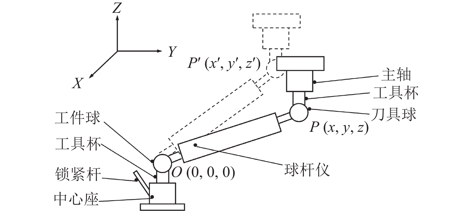
以球杆仪在XOY平面做圆弧综合误差测试为例,起始位置工件球的中心位置坐标为
$O(0,0,0)$ ,刀具球中心位置坐标为$p(x,y,z)$ ,主轴转过一定角度后,刀具球中心位置坐标为$p'(x',y',z')$ ,如图1所示。
水平安装球杆仪后,认为该状态下y=0,z=0,此时刀具球中心位置的坐标为
$ p(r,0,0) $ 。在误差存在的情况下,球杆仪实际杆长为$ {{\boldsymbol{L}}_{\text{a}}} = {\boldsymbol{T}} \cdot {{\boldsymbol{L}}_{\text{t}}} $ ,其中$ {\boldsymbol{T}} $ 为误差变换矩阵,$ {{\boldsymbol{L}}_{\text{t}}} $ 、$ {{\boldsymbol{L}}_{\text{a}}} $ 为运动前、后的刀具球中心的位置矢量,球杆仪杆长的变化量${\boldsymbol{\varDelta L = }} {{\boldsymbol{L}}_{\text{a}}}{\boldsymbol{ - }}{{\boldsymbol{L}}_{\text{t}}}$ 。刀具球中心点的综合误差${\boldsymbol{\Delta }}{\text{XY}}$ 如式(1),其中${{\boldsymbol{T}}_{{\text{SY}}}}$ 、${{\boldsymbol{T}}_{{\text{DY}}}}$ 分别表示为Y轴的静态误差变换矩阵和动态误差变换矩阵,$ {{\boldsymbol{T}}_{{\text{X0}}}} $ 和$ {{\boldsymbol{T}}_{{\text{Y0}}}} $ 分别表示为X轴、Y轴的理论运动变换矩阵,${{\boldsymbol{T}}_{\text{X}}}$ 和$ {{\boldsymbol{T}}_{\text{Y}}} $ 分别为X轴、Y轴的实际运动变化矩阵。在XOY平面上
$ {{\boldsymbol{L}}_{\text{t}}} = {[r{\text{ 0 0 1}}]^{\text{T}}} $ ,基于小角度小位移假设,利用等价无穷小替换,并将二阶及二阶以上的高阶项略去,其余角度按同样方法处理,结果有:同理,在XOZ平面和YOZ平面测试,此时刀具球中心位置的坐标分别为(r, 0, 0)、(0, r, 0)。可得XOZ平面和YOZ平面的误差结果分别为:
-
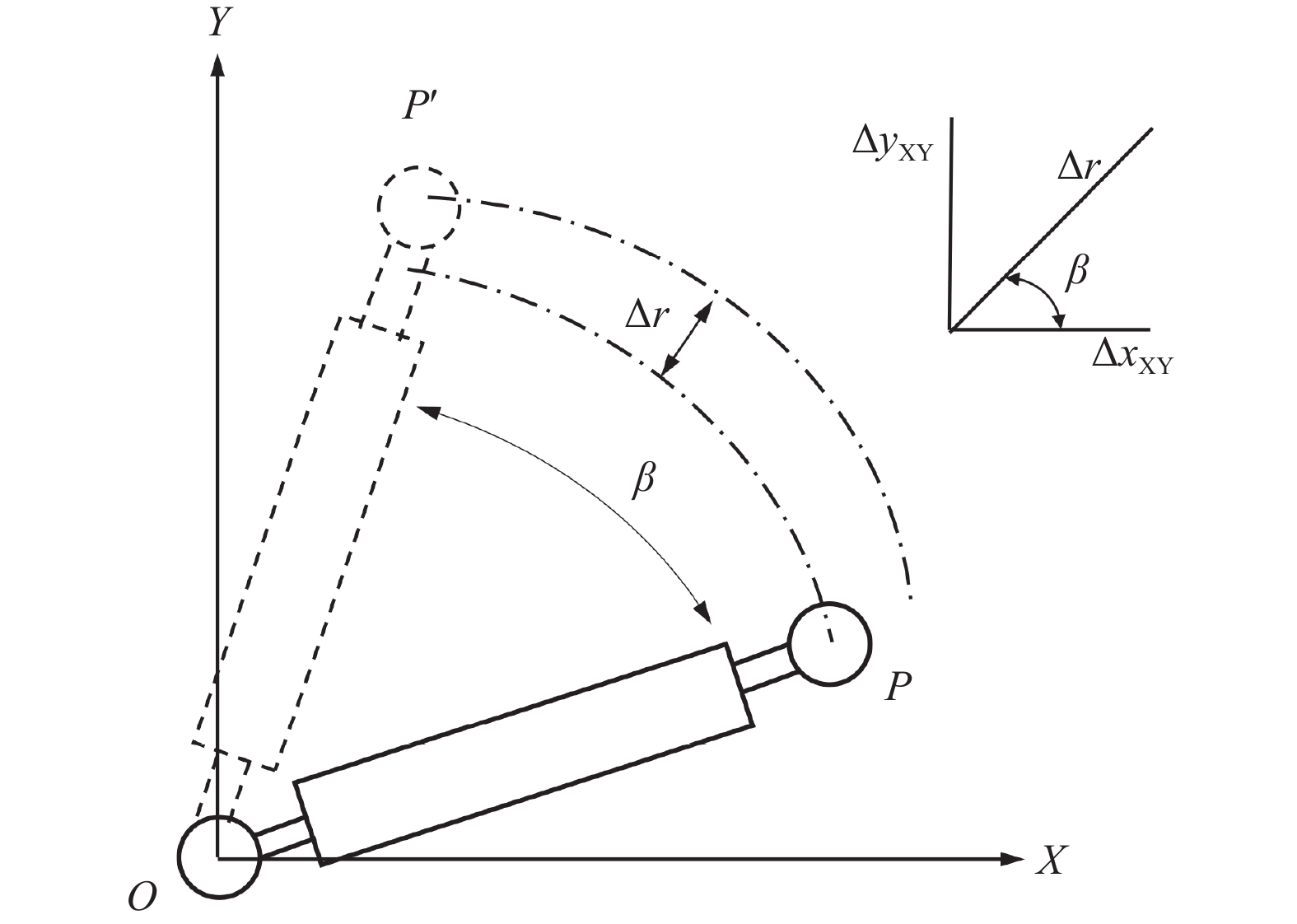
球杆仪在XOY平面做圆弧插补运动,在锁紧中心座工具杯并且保证球杆仪工件球位置固定不动的情况下,刀具球逆时针从P点移动到P'点位置,杆长的变化量为
$\Delta r$ 。杆长在X轴和Y轴上的投影如图2所示。
$ \Delta {x_{{\text{XY}}}} $ 和$ \Delta {y_{{\text{XY}}}} $ 的数学关系为:式中,β为球杆仪径向方向上从P点到P'点转过的角度;
$\Delta r$ 可在球杆仪测试过程数据文件中获得。通过分析式(4),等式右端包含线性和角度误差。为对误差进行辨识,首先需要根据误差类型采用不同方式对误差拟合。 -
静态误差不随时间变化而变化,由机床制造、装配等决定。根据刚体运动假设,可使用与机床位置坐标有关的多项式拟合静态误差。具体到机床的某个坐标轴,静态误差可表示为:
式中,Es代表静态误差;
$ {\varPhi _{\rm{s}}} $ 表示静态误差元素,即表1中的静态线性误差和静态转角误差;$p$ 代表x、y或z;$ {a_0} $ 为常数;$ {a_1} $ 、$ {a_2} $ 、···、$ {a_n} $ 为系数。 -
动态误差随时间变化而变化,是机床在工作状态下产生的误差,影响加工件的局部误差特性。动态误差不像静态误差那样与机床位置坐标有关,而与进给轴的速度和加速度相关。根据动态误差的力学特征和时变特性,将动态误差视为与运动轴速度、加速度的角频率和相位特性相关的正弦多项式[20]。具体到机床上某个坐标轴,动态误差可表示为:
式中,Ed代表动态误差;
$ {\varPhi _{\rm{d}}} $ 表示动态误差元素,即表1中的动态线性误差和动态转角误差;${({M_i})_k}$ 和${({N_j})_k}$ 为系数;$q$ 代表 x、y或z,即分别与x、y、z轴速度、加速度的角频率及相位有关;${({\omega _q})_v}$ 和${({\varphi _q})_v}$ 分别为速度的角频率和相位;${({\omega _q})_a}$ 和${({\varphi _q})_a}$ 分别为加速度的角频率和相位。 -
球杆仪测试的起始点位置的静态误差和动态误差认为是零。球杆仪在较短行程内的测量,可以采用低阶的多项式来拟合各项误差。对于X、Y方向上的静态定位误差可认为其与位置之间存在线性关系,而静态线性误差和静态转角误差相对于位置的关系较复杂,因此选取多项式前2项作为其拟合多项式。又因为球杆仪在测量时越程的存在,导致起始点的误差不为零,误差元素中应包含常数项,因此将常数项加入到静态定位误差的表达式中。动态误差由速度和加速度的角频率和相位的正弦多项式构成,选取的模型阶数越高,模型中误差的理论与误差的实际值越逼近。但模型阶数过高,增加了矩阵方程中的线性相关性,导致求解出的系数受其他系数的影响。考虑以上因素,将XOY平面误差多项式简化为表2所示。
静态误差 动态误差 X轴 $ \delta_{x x}=a_{x0}+a_{x1} x $ $ \delta_{y x}=b_{x1} x+b_{x2} x^{2} $ $ \delta_{z x}=c_{x 1} x+c_{x 2} x^{2} $ $ \begin{array}{r}\xi_{xx} = g_{x1} \sin \left(\omega _{{vx}} t+\varphi_{vx}\right) +\\ g_{x2}\left(\sin \omega_{ax} t+\varphi_{ax}\right)\end{array} $ $ \begin{array}{r}\xi_{y x}=h_{x1} \sin \left(\omega_{vx} t+\varphi_{vx}\right) +\\h_{x2}\left(\sin \omega_{ax} t+\varphi_{ax}\right)\end{array} $ $ \begin{array}{r}\xi_{zx}=i_{x1} \sin \left(\omega_{vx} t+\varphi_{vx}\right) +\\i_{x2}\left(\sin \omega_{ax} t+\varphi_{ax}\right)\end{array} $ $ \theta_{xx}=d_{x 1} x+d_{x 2} x^{2} $ $ \theta_{yx}=e_{x 1} x+e_{x 2} x^{2} $ $ \theta_{z x}=f_{x 1} x+f_{x 2} x^{2} $ $ \begin{array}{r}\varepsilon _{xx}=j_{x1} \sin \left(\omega_{vx} t+\varphi_{vx}\right) +\\j_{x2}\left(\sin \omega_{ax} t+\varphi_{ax}\right)\end{array} $ $ \begin{array}{r}\varepsilon _{yx}={k}_{x1} \sin \left(\omega_{vx} t+\varphi_{vx}\right) +\\{k}_{x 2}\left(\sin \omega_{ax} t+\varphi_{ax}\right)\end{array} $ $ \begin{array}{r} \varepsilon _{zx}=l_{x1} \sin \left(\omega_{vx} t+\varphi_{vx}\right) +\\l_{x2}\left(\sin \omega_{ax} t+\varphi_{ax}\right)\end{array} $ Y轴 $ \delta_{xy}=a_{y1} y+a_{y 2} y^{2} $ $ \delta_{yy}=b_{y 0}+b_{y1} y $ $ \delta_{zy}=c_{y 1} y+c_{y 2} y^{2} $ $\begin{array}{r} \xi_{xy}=g_{y 1} \sin (\omega_{vy} t+\varphi_{vy}) +\\g_{y 2}(\sin \omega_{ay} t+\varphi_{ay})\end{array}$ $\begin{array}{r}\xi_{yy}=h_{y1} \sin (\omega_{vy} t+\varphi_{vy}) +\\h_{y2}(\sin \omega_{ay} t+\varphi_{ay})\end{array}$ $\begin{array}{r}\xi_{z y}=i_{y 1} \sin (\omega_{vy} t+\varphi_{vy}) +\\i_{y 2}(\sin \omega_{ay} t+\varphi_{ay})\end{array}$ $ \theta_{xy}=d_{y 1} y+d_{y 2} y^{2} $ $ \theta_{yy}=e_{y1} y+e_{y2} y^{2} $ $ \theta_{zy}=f_{y1} y+f_{y 2} y^{2} $ $\begin{array}{r}\varepsilon _{xy}=j_{y 1} \sin (\omega_{vy} t+\varphi_{vy}) +\\j_{y2}(\sin \omega_{ay} t+\varphi_{ay})\end{array}$ $\begin{array}{r}\varepsilon _{yy}=k_{y 1} \sin (\omega_{vy} t+\varphi_{vy}) +\\k_{y 2}(\sin \omega_{ay} t+\varphi_{ay})\end{array}$ $\begin{array}{r}\varepsilon _{zy}=l_{y 1} \sin (\omega_{vy} t+\varphi_{vy}) +\\l_{y 2}(\sin \omega_{ay} t+\varphi_{ay})\end{array}$ 将表2中各误差多项式代入式(4),并化简整理,将其改写为矩阵形式:
对式(10),关键在于求解
$ {{\boldsymbol{B}}_{\text{1}}} $ 矩阵,而由于矩阵$ {{\boldsymbol{X}}_{{\text{me1}}}} $ 不是方阵,不能通过求$ {{\boldsymbol{X}}_{{\text{me1}}}} $ 的逆矩阵来求解,又因为该矩阵组成的方程组为超定方程组,并不能求解出唯一解,只能求解出满足各条件的最优解。针对以上问题,采用最小范数最小二乘法来求解该线性方程组的最优解。采用文献[18]的方法,假设通过实验获取了n组球杆仪数据,Xme1矩阵为 n行16列,对Xme1矩阵最大秩分解,使得Xme1=M·N,其中矩阵M行满秩,矩阵N列满秩。在求解Xme1伪逆矩阵
${{\boldsymbol{X}}_{{\text{mel}}}^{+}} $ 基础上,将XOY平面下球杆仪在y轴方向的变化值带入,可求得系数矩阵 的最小二乘解:在式(11)中,根据实际运动中的位置信息和测试时的半径可以获得矩阵
$ {{\boldsymbol{X}}_{{\text{me1}}}} $ 中$ r $ 、$ x $ 和$ y $ 的值。对于矩阵$ {{\boldsymbol{X}}_{{\text{me1}}}} $ 中形为三角函数的项,通过获取的实际位置经过微分处理得到速度和加速度随时间的变换关系,采用非线性回归的方式得到其角频率和相位。 -
误差实验测试对象为某自动化公司搭建的实验平台,测量设备选用英国雷尼绍公司的QC20-W无线球杆仪,部分参数如表3所示。
装置名 项目 内容 实验台 铭牌 无 X、Y、Z轴行程/mm 500/700/290 伺服系统 伺服驱动器、伺服电机 球杆仪 铭牌 雷尼绍QC20-W 标准长度/mm 100.000 分辨率/μm 0.1 最大采集率/s 1000 -
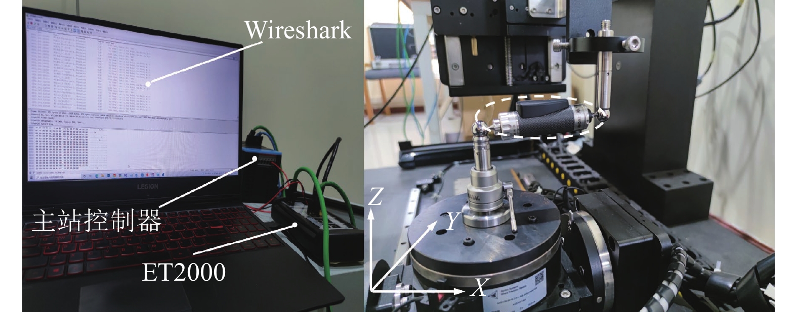
在XOY平面进行
${360^ \circ }$ 圆轨迹测试,使用网络封包分析软件Wireshark和工业以太网多道探头工具ET2000捕获现场总线上的以太网数据帧,如图3所示。对于伺服,使用在CiA 402(CAN in Automation, CiA)标准定义下的过程数据对象(process data object, PDO)来传输实时数据。通过解析伺服轴从站过程数据对象,获得实际位置脉冲数,再经由脉冲当量转换获得刀具球中心点的实际位置坐标。为了保证解算出误差的准确性,要保证球杆仪所采集数据与刀具球运行轨迹位置一一对应。根据插补速度、起始位置可以获得相邻两个数据点之间间隔的角度,并由该角度对杆长变化值分别对X方向和Y方向投影,得到两个方向上杆长的变化量。
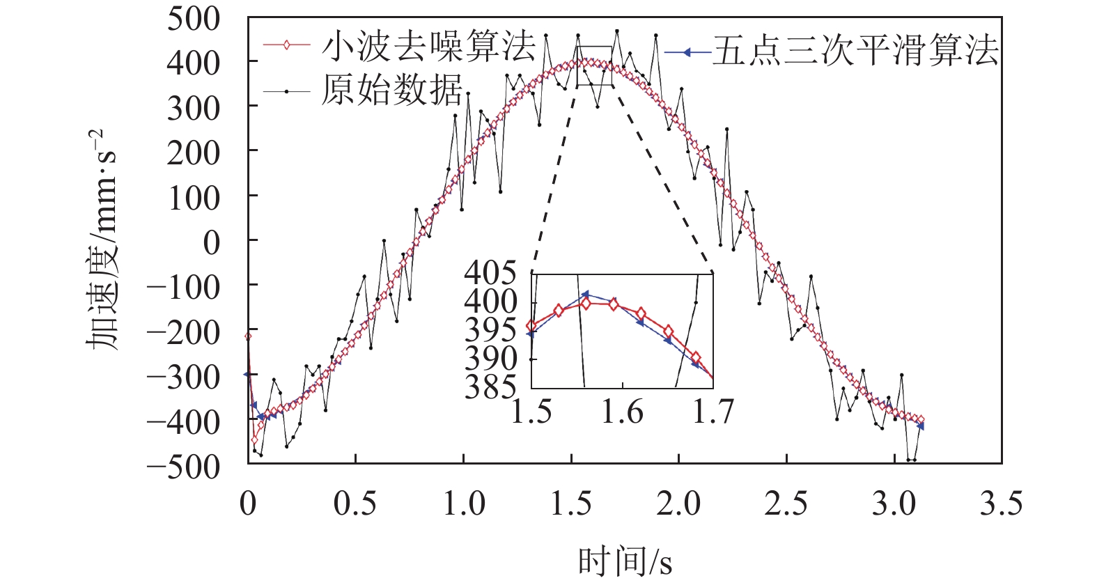
信号采集过程中无法避免噪声对数据的影响,为此在数据处理时对噪声进行识别、消除。常用的数据滤波技术包括五点三次平滑法和小波去噪,小波去噪能通过伸缩平移运算对信号逐步进行多尺度细化,最终达到高频处时间细分,低频处频率细分,自动使用时频信号分析的要求。对于小波去噪,选择近似对称的紧支集正交小波sym5、小波分解层数为5、阈值方法为硬阈值、选择sqtwolog阈值规则等参数对加速度降噪处理。对原始加速度数据做五点三次平滑和小波去噪,如图4所示。对比去噪前后的部分预测评估指标如表4,结果显示小波去噪效果好于五点三次平滑。

评价指标 原始数据 五点三次平滑 小波去噪 SSE 1.52×10⁶ 6.052×10⁴ 2.11×10⁴ R2 0.9426 0.978 0.9992 RMSE 69.91 15.75 7.237 -
在运动参数分别为速度20 mm/s、加速度100 mm/s2、加加速度500 mm/s3,环境温度为20℃进行测试。先对
$ \Delta {y_{{\text{XY}}}} $ 中的16项代求参数进行辨识,考虑到$ \Delta {x_{{\text{XY}}}} $ 里12项代求项与$ \Delta {y_{{\text{XY}}}} $ 中16项代求参数存在相同的系数。先辨识$ \Delta {y_{{\text{XY}}}} $ ,将相同系数代入$ \Delta {x_{{\text{XY}}}} $ 中简化计算环节。在XOZ平面和YOZ平面进行${220^ \circ }$ 圆弧测试。同理在该组运动参数下,利用式(5)和式(6)可辨识出XOZ平面和YOZ平面的部分误差,至此36项误差共计辨识出30项。XOY平面部分误差辨识结果表5所示。系数 值 系数 值 系数 值 系数 值 $ a_{x0} $ $ -3.125\;8 \times 10^{-5} $ $ {g}_{{x 1}} $ $ 5.295\;8 \times 10^{-4} $ $ a_{y 1} $ $ 5.436\;8 \times 10^{-3} $ $ {g}_{y1} $ $ 8.588\;7 \times 10^{-4} $ $ a_{x1} $ $ 1.999\;4 \times 10^{-3} $ $ {g}_{x2} $ $ 4.711\;7 \times 10^{-5} $ $ a_{y 2} $ $ 1.381 \times 10^{-5} $ $ {g}_{y 2} $ $ 1.351\;4 \times 10^{-4} $ $ b_{x1} $ $ 1.199\;5 \times 10^{-7} $ $ {h}_{x1} $ $ -2.043\;4 \times 10^{-8} $ $ b_{y 0} $ $ 1.673\;7 \times 10^{-6} $ $ h_{y 1} $ $ 1.183\;3 \times 10^{-8} $ $ b_{x 2} $ $ 7.625\;9 \times 10^{-12} $ $ {h}_{x2} $ $ 1.147\;0 \times 10^{-8} $ $ b_{y 1} $ $ 4.990\;9 \times 10^{-8} $ $ h_{y 2} $ $ -3.327\;7 \times 10^{-9} $ $ f_{x1} $ $ 1.199\;5 \times 10^{-5} $ $ l_{x1} $ $ -2.043\;4 \times 10^{-6} $ $ f_{y 1} $ $ 4.990\;9 \times 10^{-6} $ $ l_{y1} $ $ 1.183\;3 \times 10^{-6} $ $ f_{x2} $ $ 7.625\;9 \times 10^{-10} $ $ l_{x 2} $ $ 1.147\;0 \times 10^{-6} $ $ f_{y 2} $ $ 2.231\;4 \times 10^{-9} $ $ l_{y 2} $ $ -3.327\;7 \times 10^{-7} $ 利用同样的方法,可以辨识出XOZ平面和YOZ平面的部分静态误差和动态误差。结合表1中的36项误差,目前还存在3项静态转角误差和3项动态转角误差未辨识。由于在XOY平面、XOZ平面、YOZ平面上圆测试时,Z轴、Y轴、X轴固定不动,球杆仪安装位置分别垂直于Z轴、Y轴、X轴,可认为
$ \Delta {z_{{\text{XY}}}} = 0 $ 、$ \Delta {y_{{\text{XZ}}}} = 0 $ 、$ \Delta {x_{{\text{YZ}}}} = 0 $ 。采用式(1)可以得到
$ \Delta {z_{{\text{XY}}}} $ 的数学模型,同理可得到$ \Delta {y_{{\text{XZ}}}} $ 和$ \Delta {x_{{\text{YZ}}}} $ :式(12)中的
$ \Delta {z_{{\text{XY}}}} $ 等号右侧分为与位置坐标的误差项和与时变特性有关的误差项,由于两者特性不一致,即分别均为零的情况下,才能保证等式左侧为零。基于该处理方式,对式(13)和式(14)求解。将XOZ平面和YOZ平面中辨识出的误差代入式(12),即可辨识出剩余的6项误差,如图5所示。

-
通常在热稳定条件下,短时间内静态误差基本保持不变。在同一台机器上,随速度和加速度不同形成的被加工件精度和表面质量也各有差异。为了研究速度、加速度对机床动态误差的影响规律,分别设计了12组不同方案,均在XOY平面360°圆弧插补运动,运动参数如表6所示。
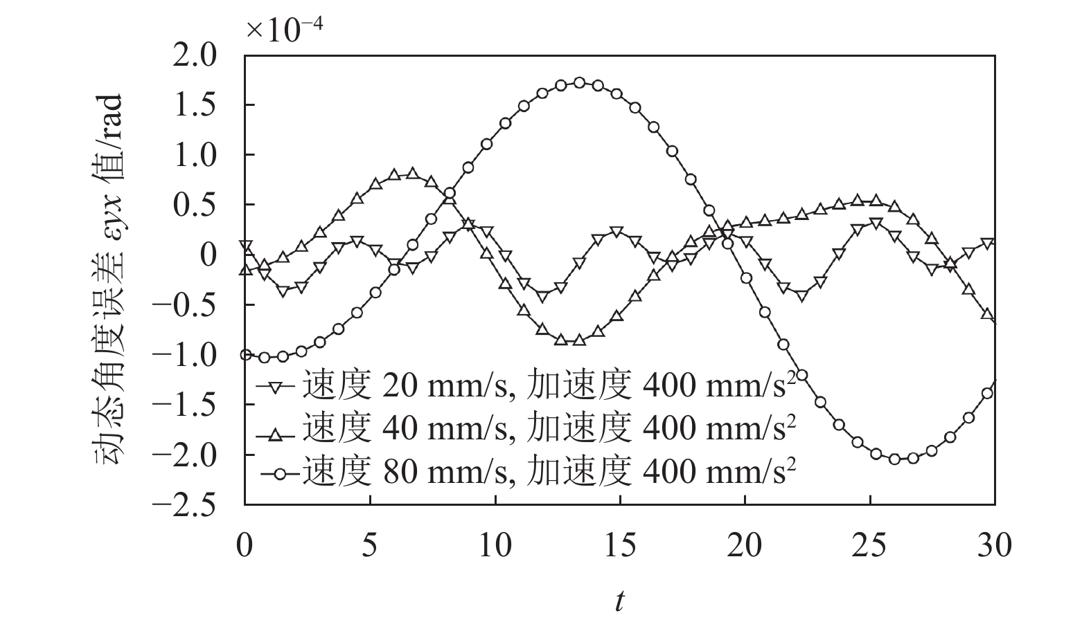
序号 运动参数 序号 运动参数 速度/mm·s−1 加速度/mm·s−2 速度/mm·s−1 加速度/mm·s−2 1 10 50 7 40 200 2 10 100 8 40 400 3 10 200 9 40 800 4 20 100 10 80 400 5 20 200 11 80 800 6 20 400 12 80 1600 通过对比序号6、8、10,在加速度均为400 mm/s2,速度由20 mm/s上升至40、80 mm/s,可得到不同速度对动态误差的影响规律。在加速度均为400 mm/s2,速度分别为20、40、80 mm/s,时间为13.34 s下对应的动态角度误差
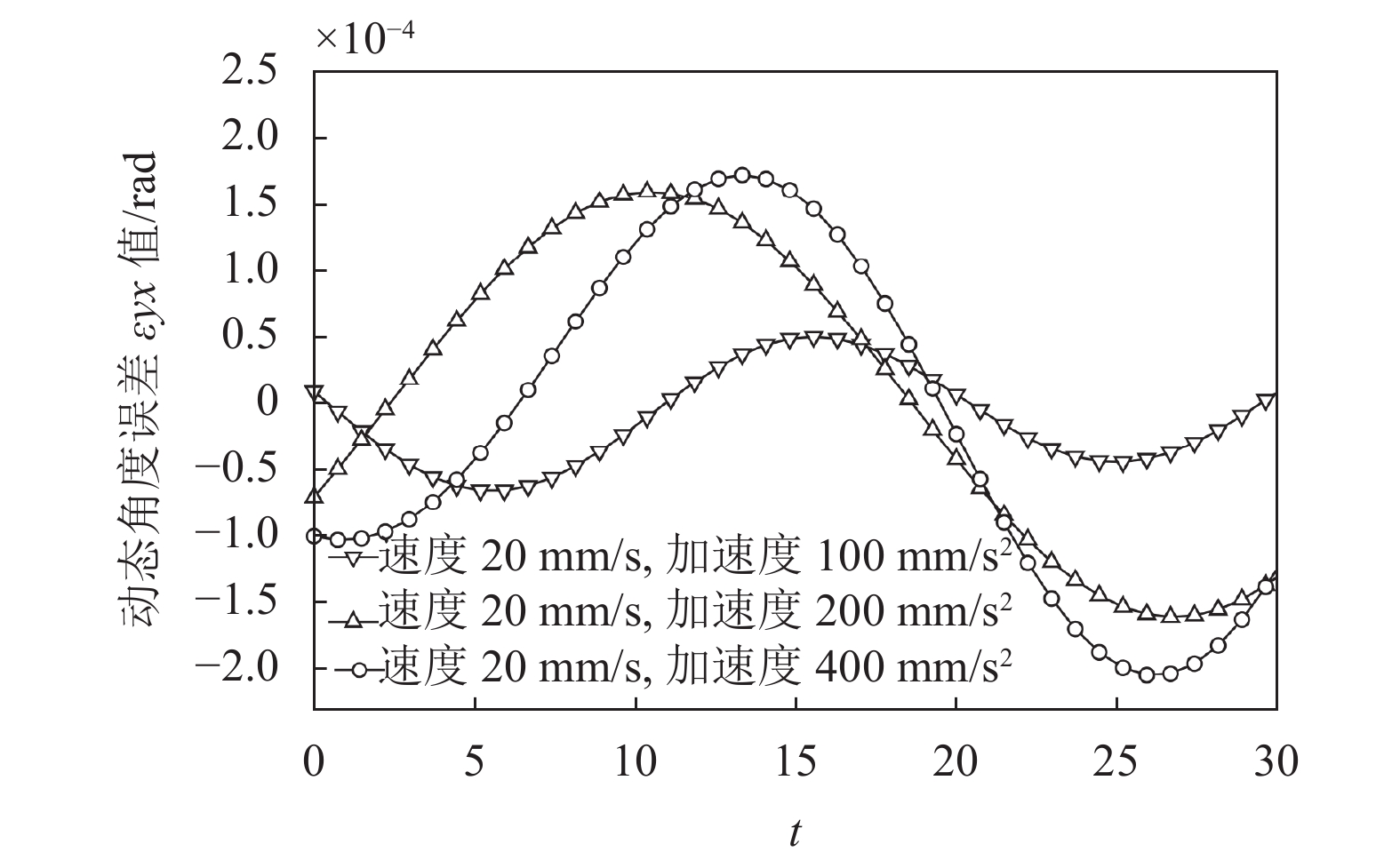
$ {\varepsilon _{yx}} $ 分别为0、$ - 8.638 \times {10^{ - 5}}$ 和$1.731 \times {10^{ - 4}}$ rad,如图6所示。速度由20 mm/s增大至40 mm/s时,误差的绝对值增大了$8.0003 \times {10^{ - 5}}$ rad,误差值增大了1 254.555 6%;速度由40 mm/s增大至80 mm/s时,误差的绝对值增大了$8.672 \times {10^{ - 5}}$ rad,增大了100.393 6%。如图7,在速度为20 mm/s,加速度分别为100、200、400 mm/s2参数下,时间为13.34 s时的动态角度误差分别为3.763×10⁻⁵、1.370×10⁻⁴、1.731×10⁻⁴ rad,对比图6和图7可知,速度对动态角度误差
$ {\varepsilon _{yx}} $ 的影响比加速度的影响大。
由图6和图7可以看出,速度和加速度对动态角度误差
$ {\varepsilon _{yx}} $ 均有影响,且速度对动态误差的影响更明显。表7中,在加速度为400 mm/s2、速度分别为20、40、80 mm/s下,分析速度对动态误差的影响,动态误差占总误差的比例分别为2.13%、11.74%和49.15%。在速度为40 mm/s、加速度分别为200和800 mm/s2下分析加速度对动态误差的影响,动态误差在总误差中的比例分别为22.72%和26.83%。这也说明了在速度较大或速度较小但加速度较大的情况下,动态误差对被加工件的表面质量影响较大。

序号 动态线性误差值/mm 动态角度误差值/rad 动态误差占比/% $ \xi _{xx} $ $ {\xi}_{yy} $ $ {\xi}_{zz} $ $ \varepsilon _{xx} $ $ \varepsilon _{yy} $ $ \varepsilon _{zz} $ 6 $ 2.827\;5 \times 10^{-5} $ 0 0 $ -1.451\;5 \times 10^{-5} $ $ 6.242\;4 \times 10^{-5} $ $ 1.232\;8 \times 10^{-5} $ 2.13 7 $ 9.665\;7 \times 10^{-4} $ $ -2.816\;7 \times 10^{-4} $ $ -3.577\;5 \times 10^{-4} $ $ -7.724\;0 \times 10^{-4} $ $ 6.366\;7 \times 10^{-4} $ $ -7.667\;5 \times 10^{-4} $ 22.72 8 $ 2.172\;0 \times 10^{-4} $ $ 1.335\;9 \times 10^{-4} $ $ -5.259\;1 \times 10^{-5} $ $ 8.212\;5 \times 10^{-4} $ $ -6.576\;2 \times 10^{-4} $ 0 11.74 9 $ 8.284\;2 \times 10^{-3} $ $ -4.295\;2 \times 10^{-4} $ $ -2.816\;7 \times 10^{-4} $ $ 6.298\;3 \times 10^{-5} $ $ -1.428\;7 \times 10^{-4} $ $ 6.130\;5 \times 10^{-4} $ 26.83 10 $ 0.010\;8 $ $ 0.009\;6 $ $ 0.006\;6 $ $ -2.511\;9 \times 10^{-5} $ $ 1.231\;9 \times 10^{-4} $ $ -1.539\;4 \times 10^{-4} $ 49.15 -
本文以机床误差的建模和分析作为研究内容,建立了机床动、静态误差模型,通过模型求解出机床的误差表达式,并进行了实验验证。主要研究总结如下。
1) 根据静态误差和动态误差的特性不同,选择不同的方式拟合两类误差。在误差的辨识过程中,为了获取速度和加速度的角频率和相位,采用微分的方式处理位置与时间的数学关系,进一步获得速度、加速度与时间的关系。
2) 对加速度原始数据,采用五点三次平滑滤波和小波变换去噪处理。在小波去噪中选择四种不同阈值规则对信号消噪,在选用了sqtwolog阈值规则后,决定系数R2提高了5.877%,均方根误差RMSE降低了81.76%。
3) 在速度分别为20、40、80mm/s时,动态误差所占总误差的比例为2.13%、11.74%和49.15%。在速度为40 mm/s、加速度分别为200和800 mm/s2下分析加速度对动态误差的影响,动态误差在总误差中的比例分别为22.72%和26.83%。即速度和加速度都作为影响动态误差的重要因素,且速度的影响更大。
Measurement and Identification of Dynamic Errors for Bus CNC Machine Tools
doi: 10.12178/1001-0548.2022013
- Received Date: 2022-01-07
- Rev Recd Date: 2022-09-06
- Available Online: 2023-04-03
- Publish Date: 2023-03-28
-
Key words:
- double ball-bar /
- dynamic errors /
- homogeneous coordinates transformation /
- least-squares theory /
- wavelet transform
Abstract: In high speed machining with multi-axis linkage, the dynamic error of machine tool caused by motion parameters is an important factor to produce machining errors. In this paper, the dynamic error and static error models of EtherCAT bus CNC machine tools are established by using the rod instrument QC20-W and the industrial Ethernet probe tool ET2000 as measuring tools. Firstly, based on the homogeneous coordinate transformation theory, the mathematical relationship among the rod length variation and the dynamic and static errors of the machine tool is established. Then, according to the different characteristics of the two kinds of errors, we construct the static error polynomial expressed by coordinate positions and the dynamic error low order sine polynomial expressed by velocity, acceleration angular frequency, and phase. In order to obtain the angular frequency and phase information of velocity and acceleration in sinusoidal polynomial, Wireshark and ET2000 are used to capture the position information of axis, and the velocity and acceleration are obtained by differentiating. Wavelet transform is used to reduce the noise in position information. Finally, the least square theory is used to solve the unknown coefficients in the error expression. The results show that instruction speed is the main factor of dynamic error, and acceleration is the secondary factor. When the acceleration is constant and the instruction speed increases from 20 mm/s to 40 mm/s and 80 mm/s, the proportion of dynamic error in the total error increases from 2.13% to 11.74% and 49.15%. When the command speed is unchanged and the acceleration increases from 200 mm/s2 to 800 mm/s2, the proportion of dynamic error increases from 22.72% to 26.83%, respectively.
| Citation: | YIN Guowei, LI Xianglong, CHEN Bing. Measurement and Identification of Dynamic Errors for Bus CNC Machine Tools[J]. Journal of University of Electronic Science and Technology of China, 2023, 52(2): 313-320. doi: 10.12178/1001-0548.2022013

|


 DownLoad: