Volume 45 Issue 6
Dec.  2016
Article Contents

HUANG Bo, LI Xun-bo, ZENG Zhi, YAN Ming-ming, LI Jun, YIN Zhi-yu. Thermal Fatigue Life Prediction for Laser Soldering Joints of Electrical Connectors[J]. Journal of University of Electronic Science and Technology of China, 2016, 45(6): 1027-1032. doi: 10.3969/j.issn.1001-0548.2016.06.026
Citation: HUANG Bo, LI Xun-bo, ZENG Zhi, YAN Ming-ming, LI Jun, YIN Zhi-yu. Thermal Fatigue Life Prediction for Laser Soldering Joints of Electrical Connectors[J]. Journal of University of Electronic Science and Technology of China, 2016, 45(6): 1027-1032. doi: 10.3969/j.issn.1001-0548.2016.06.026

Thermal Fatigue Life Prediction for Laser Soldering Joints of Electrical Connectors

doi: 10.3969/j.issn.1001-0548.2016.06.026
  • Received Date: 2015-06-15
  • Rev Recd Date: 2016-03-01
  • Publish Date: 2016-11-01
  • Mechanical properties of Micro-USB electrical connectors is affected by instantaneous power on or off caused by hot-plugging. In order to further understand the failure behavior of electrical connectors under thermal cycling, it is necessary to carry out the fatigue life prediction for laser soldering joints of Micro-USB electrical connectors under heat acceleration test. Firstly, the finite element model of Micro-USB electrical connectors is established. The mechanical behavior of solder joints under cyclic thermal loading is described by using the Anand constitutive equation. Then, the stress or strain distribution is analyzed by means of ANSYS software. Finally, the thermal fatigue life under thermal cycling can be calculated by using the Coffin-Manson equation based on plastic strain. The results show that the maximum stress or strain occurs at the place of the middle solder joint contacting with metal Pin when laser soldering joints of electrical connectors are subjected to thermal cycling. Its fatigue life is lowest, only 1 146 times. Meanwhile, the risk of failure can be determined. The conclusions can provide a theoretical reference for the design, manufacture and testing of electrical connectors.
  • [1] 邹翔, 彭清华.连接器行业最新发展趋势分析[J].机电元件, 2014, 34(5):45-48. http://www.cnki.com.cn/Article/CJFDTOTAL-JDYG201405011.htm

    ZOU Xiang, PENG Qing-hua. Analysis on the latest development trend of connector industry[J]. Electromechanical Components, 2014, 34(5):45-48. http://www.cnki.com.cn/Article/CJFDTOTAL-JDYG201405011.htm
    [2] GAILUS M W. High speed, high density electrical connector:USA, U.S.8, 371, 875[P]. 2013-02-12.
    [3] 杨奋为.军用电连接器创新发展研讨[J].机电元件, 2012, 32(4):52-61. http://www.cnki.com.cn/Article/CJFDTOTAL-JDYG201204016.htm

    YANG Fen-wei. Discussion on innovative development of military electrical connector[J]. Electromechanical Components, 2012, 32(4):52-61. http://www.cnki.com.cn/Article/CJFDTOTAL-JDYG201204016.htm
    [4] 高辉.手机电池连接器的设计应用与发展趋势[J].机电元件, 2014, 34(1):49-54. http://www.cnki.com.cn/Article/CJFDTOTAL-JDYG201401012.htm

    GAO Hui. Design and trend of mobile phone battery connector[J]. Electromechanical Components, 2014, 34(1):49-54. http://www.cnki.com.cn/Article/CJFDTOTAL-JDYG201401012.htm
    [5] CONWAY P P, KALANTARY M R, WILLIAMS D J. Experimental investigation of the formation of surface mount solder joints[J]. Journal of Electronic Packaging, 1996, 118(4):223-228. doi:  10.1115/1.2792156
    [6] MURAKAMI K, ADACHI A, MORIHIRO Y, et al. Laser soldering for fine-pitch leads in SMT assembly[J]. Laser Materials Processing, 1994, 2500:388.
    [7] 张昕, 薛松柏, 韩宗杰.激光软钎焊技术在高密度封装器件无铅连接中的应用[J].焊接, 2007, (11):21-26. http://www.cnki.com.cn/Article/CJFDTOTAL-HAJA200711006.htm

    ZHANG Xin, XUE Song-bai, HAN Zong-jie. Review on application of laser soldering technology to join high density packaging device with lead-free solder[J]. Welding & Joining, 2007, (11):21-26. http://www.cnki.com.cn/Article/CJFDTOTAL-HAJA200711006.htm
    [8] 罗勤明.多焊点Hot-bar锡焊工艺参数优化[D].上海:上海交通大学, 2009. http://cdmd.cnki.com.cn/Article/CDMD-10248-2009225860.htm

    LUO Qin-ming. Multi-spot Hot-bar soldering process parameters optimization[D]. Shanghai:Shanghai JiaoTong University, 2009. http://cdmd.cnki.com.cn/Article/CDMD-10248-2009225860.htm
    [9] KANG H S, NOH J, CHOI J Y. Study on laser soldering for manufacturing flip chip packaging[C]//Proceedings of the International Conference of Manufacturing Technology Engineers (ICMTE). Seoul:Korean Society of Manufacturing Technology Engineers, 2014.
    [10] LEE O S, HUR M J, PARK Y C, et al. Vibration fatigue reliability of lead and lead-free solder joint by FORM/SORM[J]. Key Engineering Materials, 2007, 345-346(2):1393-1396. https://www.researchgate.net/publication/250325489_Vibration_fatigue_reliability_of_lead_and_lead-free_solder_joint_by_FORMSORM
    [11] YANG J, UME I C. Thermomechanical reliability study of flip-chip solder bumps:Using laser ultrasound technique and finite element method[C]//58th Electronic Components and Technology Conference, ECTC 2008. New York, USA:IEEE, 2008.
    [12] EKPU M, BHATTI R, OKEREKE M I, et al. Fatigue life of lead-free solder thermal interface materials at varying bond line thickness in microelectronics[J]. Microelectronics Reliability, 2014, 54(1):239-244. doi:  10.1016/j.microrel.2013.08.006
    [13] PANG J, XIONG B S, LOW T H. Comprehensive mechanics characterization of lead-free 95.5Sn-3.8Ag-0.7Cu solder[J]. Micromaterials and Nanomaterials, 2004, 3:86-93.
    [14] 吴玉秀, 薛松柏, 张玲, 等. QFP组件的优化模拟及焊点热疲劳寿命的预测[J].焊接学报, 2006, 27(8):99-102. http://www.cnki.com.cn/Article/CJFDTOTAL-HJXB200608025.htm

    WU Yu-xiu, XUE Song-bai, ZHANG Ling, et al. Optimum simulation and prediction on thermal fatigue life of solder joints of QFP devices[J]. Transactions of the China Welding Institution, 2006, 27(8):99-102. http://www.cnki.com.cn/Article/CJFDTOTAL-HJXB200608025.htm
    [15] PAYDAR N, TONG Y, AKAY H U. A finite element study of factors affecting fatigue life of solder joints[J]. Journal of Electronic Packaging, 1994, 116(4):265-273. doi:  10.1115/1.2905697
    [16] ENGELMAIER W. Functional cycles and surface mounting attachment reliability[J]. Circuit World, 1985, 11(3):61-72. doi:  10.1108/eb046004
    [17] ZENG Z, LI X, WANG R, et al. Numerical modeling and optimization of laser soldering for Micro-USB electric connector[J]. International Journal of Numerical Modelling:Electronic Networks, Devices and Fields, 2015, 28(2):175-188. doi:  10.1002/jnm.v28.2
    [18] 刘毅. Micro-USB电子连接器激光软钎焊接工艺研究及数值模拟[D].成都:电子科技大学, 2013. http://cdmd.cnki.com.cn/Article/CDMD-10614-1013329222.htm

    LIU Yi. The process research and numerical simulation of laser soldering about Micro-USB connector[D]. Chengdu:University of Electronic Science and Technology of China, 2013. http://cdmd.cnki.com.cn/Article/CDMD-10614-1013329222.htm
    [19] 闫青亮. PBGA无铅焊点可靠性的有限元模拟与寿命预测[D].天津:天津大学, 2007. http://cdmd.cnki.com.cn/Article/CDMD-10056-2008183353.htm

    YAN Qing-liang. Finite element simulation and life prediction for reliability of lead-free solder in PBGA[D]. Tianjin:Tianjin University, 2007. http://cdmd.cnki.com.cn/Article/CDMD-10056-2008183353.htm
    [20] LAU J H, LEE S R. Modeling and analysis of 96.5 Sn-3.5 Ag lead-free solder joints of wafer level chip scale package on buildup microvia printed circuit board[J]. IEEE Transactions on Electronics Packaging Manufacturing, 2002, 25(1):51-58. doi:  10.1109/TEPM.2002.1000483
    [21] MOON K W, BOETTINGER W J, KATTNER U R, et al. Experimental and thermodynamic assessment of Sn-Ag-Cu solder alloys[J]. Journal of Electronic Materials, 2000, 29(10):1122-1136. doi:  10.1007/s11664-000-0003-x
    [22] ANAND L. Constitutive equations for hot-working of metals[J]. International Journal of Plasticity, 1985, 1(3):213-231. doi:  10.1016/0749-6419(85)90004-X
    [23] JEN Y M, FANG C K, YEH Y H. Effect of size of lid-substrate adhesive on reliability of solder balls in thermally enhanced flip chip PBGA packages[J]. IEEE Transactions on Components and Packaging Technologies, 2006, 29(4):718-726. doi:  10.1109/TCAPT.2006.885927
    [24] AMAGAI M, WATANABE M, OMIYA M, et al. Mechanical characterization of Sn-Ag-based lead-free solders[J]. Microelectronics Reliability, 2002, 42(6):951-966. doi:  10.1016/S0026-2714(02)00017-3
    [25] 张亮. SnAgCu系无铅焊点可靠性及相关理论研究[D].南京:南京航空航天大学, 2011. http://cdmd.cnki.com.cn/Article/CDMD-10287-1012016592.htm

    ZHANG Liang. Study on reliability of SnAgCu based lead-free soldered joint and related theory[D]. Nanjing:Nanjing University of Aeronautics and Astronautics, 2011. http://cdmd.cnki.com.cn/Article/CDMD-10287-1012016592.htm
  • 加载中
通讯作者: 陈斌, bchen63@163.com
  • 1. 

    沈阳化工大学材料科学与工程学院 沈阳 110142

  1. 本站搜索
  2. 百度学术搜索
  3. 万方数据库搜索
  4. CNKI搜索

Figures(5)  / Tables(3)

Article Metrics

Article views(4434) PDF downloads(152) Cited by()

Related
Proportional views

Thermal Fatigue Life Prediction for Laser Soldering Joints of Electrical Connectors

doi: 10.3969/j.issn.1001-0548.2016.06.026

Abstract: Mechanical properties of Micro-USB electrical connectors is affected by instantaneous power on or off caused by hot-plugging. In order to further understand the failure behavior of electrical connectors under thermal cycling, it is necessary to carry out the fatigue life prediction for laser soldering joints of Micro-USB electrical connectors under heat acceleration test. Firstly, the finite element model of Micro-USB electrical connectors is established. The mechanical behavior of solder joints under cyclic thermal loading is described by using the Anand constitutive equation. Then, the stress or strain distribution is analyzed by means of ANSYS software. Finally, the thermal fatigue life under thermal cycling can be calculated by using the Coffin-Manson equation based on plastic strain. The results show that the maximum stress or strain occurs at the place of the middle solder joint contacting with metal Pin when laser soldering joints of electrical connectors are subjected to thermal cycling. Its fatigue life is lowest, only 1 146 times. Meanwhile, the risk of failure can be determined. The conclusions can provide a theoretical reference for the design, manufacture and testing of electrical connectors.

HUANG Bo, LI Xun-bo, ZENG Zhi, YAN Ming-ming, LI Jun, YIN Zhi-yu. Thermal Fatigue Life Prediction for Laser Soldering Joints of Electrical Connectors[J]. Journal of University of Electronic Science and Technology of China, 2016, 45(6): 1027-1032. doi: 10.3969/j.issn.1001-0548.2016.06.026
Citation: HUANG Bo, LI Xun-bo, ZENG Zhi, YAN Ming-ming, LI Jun, YIN Zhi-yu. Thermal Fatigue Life Prediction for Laser Soldering Joints of Electrical Connectors[J]. Journal of University of Electronic Science and Technology of China, 2016, 45(6): 1027-1032. doi: 10.3969/j.issn.1001-0548.2016.06.026
  • 随着国内外互连产业的迅猛发展,作为各类电子系统中不可或缺的重要配套基础元件--电连接器,已表现出向微型化、高密度、高速传输等方向的发展趋势,其市场潜力巨大[1-2]。目前,电连接器在航天及军用、通信、汽车、工业设备、电脑及其外设等几大领域内得到广泛应用[3-4]。由于电连接器在系统中发挥着电路连接、信号传递的重要作用,一旦其发生故障必然会影响到连接设备甚至整个系统的正常工作。而电连接器内部焊点又是影响电连接器自身可靠性的关键因素之一。由于采用传统的手工锡焊、热风焊或自动烙铁锡焊(hot bar)进行电连接器焊接时,对导线的损伤将不可避免,且极易形成相邻焊点的引线间发生“桥连”[5]。而激光软钎焊工艺易于实现自动化控制,能够满足电连接器与引线进行焊点互连的要求,使可焊精度达到微米级,从而极大地提高焊点的疲劳寿命[6-9]。在关于焊点疲劳寿命预测的研究方面,文献[10]结合有限元仿真对不同材料运用一阶、二阶可靠性分析方法,重点研究了焊点失效模型的可靠性问题。文献[11]利用激光超声技术与有限元方法对焊点在热循环加载条件下的可靠性进行了研究。文献[12]采用有限元建模分析了三种不同焊料的疲劳寿命,得到了疲劳寿命与焊接热界面厚度之间的变化关系。目前国内外对电连接器焊点寿命预测的研究成果相对较少,因此,研究激光软钎焊焊点疲劳寿命问题对提高整个电连接器的质量与可靠性将具有重要的意义。

  • 本文在针对激光软钎焊焊点进行寿命预测时,主要是通过采用有限元方法确定激光软钎焊焊点在温度循环过程中的塑性应变范围,而以塑性应变为基础模型的寿命预测方法,即Coffin-Manson预测方法,可以通过解析法或有限元方法确定其塑性应变变化范围。因此,本文采用Coffin-Manson方法对焊点进行热疲劳寿命预测。

    Coffin-Manson方程的表达式如下[13]

    式中, ${N_f}$ 为焊点的疲劳寿命; $\Delta \gamma $ 为等效非弹性剪应变范围; ${\varepsilon _f}$ 为疲劳韧性系数;C为疲劳韧性指数。 $\Delta \gamma $ 与焊点在每个周期内累计塑性应变最大范围 $\Delta {\varepsilon _p}$ 之间具有如下关系[14]

    另外,疲劳韧性指数C可通过下式进行计算[15]

    式中,f为循环频率, $1 \le f \le 1{\rm{ }}000$ [16]; ${T_m}$ 为热循环平均温度,且 ${T_m}$ 值为:

    式中, ${T_{\max }}$ 、 ${T_{\min }}$ 分别为选用标准的热循环试验温度的最大温度值及最小温度值。

    确定参数 ${\varepsilon _f}$ 、C后,再通过有限元方法,分析焊点在热循环过程中塑性应变的变化情况,得出最大塑性应变范围,并计算出 $\Delta \gamma $ 。将已得到的各参数值代入式(1),最终求出激光软钎焊焊点的热疲劳寿命。

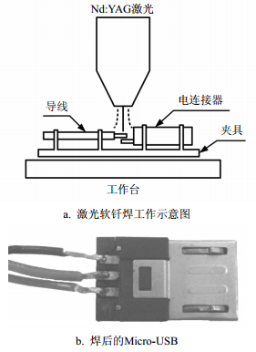
  • 本文采用了武汉楚天工业激光设备有限公司生产的Nd:YAG激光焊接机(JHM-1GX-400D)。在工艺参数激光频率2 Hz、脉宽1.0~2.5 ms、离焦量0~1 mm以及电流120~150 A下,得到的Micro-USB激光软钎焊焊点经抗拉强度测试,焊点所能承受的拉伸力高于行业标准规定的20 N,证明了该激光软钎焊工艺已具备可行性[17-18]。激光软钎焊的工作情况如图 1a所示,通过利用高能量的激光脉冲对Micro-USB电连接器焊接区域进行局部加热,激光辐射的能量在极短的时间内使被焊部位快速形成一个高度集中的热源区,致使焊料熔化形成焊点,得到的Micro-USB试样如图 1b所示。

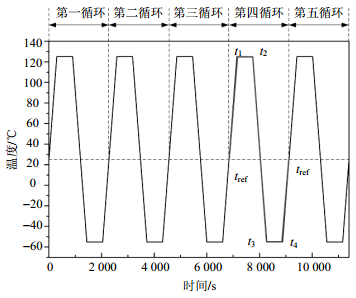
    依据美国军方采用的MIL-STD-883标准,对电连接器进行热加速试验,如图 2所示。其中,tref表示25℃常温时刻,有研究表明,在周期性加载条件下tref的选取对应力应变分析结果无影响[19]。另外,t1t2分别表示125℃高温保温开始与结束时刻;t3t4分别表示-55℃低温保温开始与结束时刻。高、低温阶段的保温时长均为600 s。

  • 电连接器有限元模型中焊点采用Visco107单元,适合于粘塑性变化大的寿命分析;其他部分均采用Solid45单元,该单元适用于结构的应力应变分析。电连接器封装材料主要为硬橡胶和碳素钢,金属Pin为轧制纯铜,导线为纯铜,焊点材料为Sn3.5Ag0.75Cu,各部分材料属性如表 1所示。其中,Sn3.5Ag0.75Cu焊点的弹性模量和热膨胀系数表达式可根据文献[20]推导得出,两者均是温度(T/℃)的函数,随着温度的变化而发生改变。

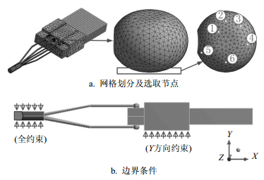
    材料属性 弹性模量/Pa 泊松比 导热系数/m·k 热膨胀系数/ppm·K-1
    纯铜 8.8×10¹⁰ 0.30 300 16.7
    轧制纯铜 9.0×10¹⁰ 0.30 397 17.7
    硬橡胶 2.0×10¹⁰ 0.39 0.3 100
    碳素钢 8.8×10¹⁰ 0.30 350 12.32
    Sn3.5Ag 0.75Cu 54 900-67.14T-0.058 7T2 0.40 73 23.9+0.203 9T

    焊点在随温度的周期性变化过程中将发生不同的粘塑性应力应变行为,为了保证分析结果的准确性,对焊点部分网格进行了加密处理,如图 3a所示。同时,依据实际工况,电连接器在插合工作状态下保持固定不动,垂直方向(即Y方向)上无相对位移,塑封完好的导线之间同样保持固定,因此,将同轴线缆末端及塑封外壳底面Y方向分别施加固定约束,其边界条件如图 3b所示。

  • Micro-USB电连接器软钎焊焊点材料Sn3.5Ag 0.75Cu的熔点约为217℃[21],而通常电子元件的工作温度达到钎料熔点的0.5倍时,钎料将会表现为粘塑性。由于焊点受到循环温度作用,其不仅表现为塑性变形,蠕变变形也伴随发生。因此,采用Anand统一性方程可以很好地将二者结合起来考虑,能够更好地描述焊点材料应力应变等力学行为。Anand方程的数学表达式如下[22]

    式中,A为前幂指数因子;Q/R为激活能与玻尔兹曼常数之比;T为温度; $\xi $ 为应力因子;m为应变敏感系数。

    另外,形变阻抗演化方程表示如下[23]

    式中,h0为硬化/软化系数;a为应变指数; $\hat s$ 为饱和变形阻抗系数;n为变形率敏感系数。

    式(5)~式(7)中各参数的具体数值如表 2所示。将Anand方程作为描述Sn3.5Ag0.75Cu焊点的本构关系模型,并结合有限元模拟方法,从而可对焊点的应力应变分布情况进行针对性分析。

    参数 Sn3.5Ag0.75Cu
    s0/MPa 1.04
    Q/R·K-1 8 400
    A/s-1 4.61×10⁶
    $\xi $ 0.038
    m 0.162
    $\hat s{\rm{/MPa}}$ 1.04
    n 4.61×10⁻³
    a 1.56
    h0/MPa 3 090
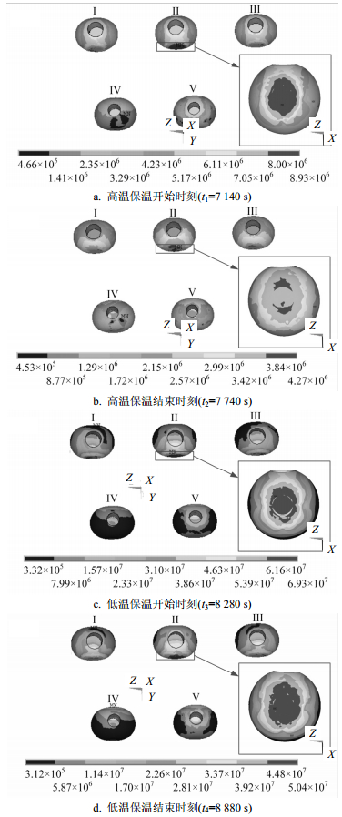
  • 由于在热循环作用下,焊点通常历经至第四循环时受力情况趋于稳定[19],因此针对在第四循环温度变化时焊点的应力分布情况进行分析,分析结果如图 4所示。需要说明的是,图中各焊点上的圆孔位置是导线连入焊点内所形成的,为便于观察,未将导线在图中进行显示。

    高温保温阶段,图 4a中反映了第四循环高温保温开始时刻t1时,各焊点的应力分布情况。从图中可以看出,应力较大的区域主要集中在焊点Ⅰ、Ⅱ、Ⅲ上,焊点Ⅳ、Ⅴ上的应力相对较小。其中,焊点Ⅱ的应力最大,且最大值为8.93 MPa。图 4b是高温保温结束时刻t2时的应力云图。与高温保温开始时刻相比较,各焊点的应力出现下降并且应力范围也相应变小,这主要是因为在高温保温期间焊点应力松弛所引起。5个焊点应力趋于均匀分布,并且主要集中在焊点底部区域。该时刻焊点所受应力降至整个温度循环过程中的最小值,其等效应力值为4.27 MPa。

    低温保温阶段,低温保温开始时刻t3及结束时刻t4时焊点的应力分布情况分别如图 4c图 4d所示。在图 4c中,等效应力主要集中于焊点与金属Pin相互连接处,焊点Ⅱ应力分布突出,其应力范围从底部两端向底部中心汇聚,此时等效应力达到整个循环过程中的最大值69.31 MPa。由于焊点经历了从高温到低温的温度变化过程,使得焊点材料、金属Pin材料之间热膨胀系数失配明显,因而造成焊点的应力水平相对较高。图 4d中,由于低温保温作用使得焊点所受应力出现松弛现象而逐渐下降。此刻等效应力最大值为50.39 MPa。各焊点的外围区域应力较小,但焊点底部应力分布范围在进一步扩大,主要集中于焊点底部。

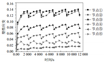
  • 从应力分析中得知,在热循环载荷作用下焊点Ⅱ出现应力集中。因此,焊点Ⅱ是可能发生失效的危险焊点,在该焊点与金属Pin相互接触的部位选取了6个不同的节点,已在图 3a中注明。选取这些节点的主要依据是由于在相同的条件下,不同焊点区域的节点的塑形应变不同,而这些节点均是位于焊点底部易发生塑形应变且变化相对较大的区域内。这些节点的塑形应变情况如图 5所示。

    由于弹性应变很小,起主导作用的主要是由塑性应变引起。根据图 5的应变结果得出各个节点的塑性应变最大范围后,利用式(2)计算出 $\Delta \gamma $ 。疲劳韧性系数 ${\varepsilon _f}$ 取0.325[25]。由式(3)和式(4)计算得到疲劳韧性指数C的值。再将以上各参数值代入式(1),得出热疲劳寿命的计算结果,如表 3所示。

    名称 等效非弹性剪应变范围 $\Delta \gamma \times {10^{ - 2}}$ 疲劳韧性系数 ${\varepsilon _f}$ 疲劳韧性指数C 热疲劳寿命 ${\varepsilon _f}$ /次
    节点① 3.083 0.325 -0.394 1 146
    节点② 2.873 0.325 -0.394 1 371
    节点③ 2.624 0.325 -0.394 1 726
    节点④ 2.434 0.325 -0.394 2 088
    节点⑤ 0.697 6 0.325 -0.394 49 799
    节点⑥ 0.799 8 0.325 -0.394 35 198

    表 3中节点的热疲劳寿命计算结果可知,塑性应变变化越大,寿命越短。节点①塑性应变变化范围最大,寿命计算值最低,因此,焊点将极易从该处开始萌生裂纹,并最终导致失效发生。

  • 1) 由于实际工作中通过试验的手段得到激光软钎焊焊点的寿命存在较大的困难,因而采用ANSYS模拟分析得到焊点应力应变结果,再结合Coffin-Manson公式进行寿命估算。该方法对电子封装软钎焊焊点的疲劳寿命预测具有一定的理论指导意义。

    2) 由于受到应力集中的影响,裂纹萌生的危险部位位于焊点II与金属Pin相互接触处,其最大等效应力为69.31 MPa。

    3) 基于激光软钎焊焊点危险部位的塑形应变,针对不同节点运用Coffin-Manson公式分别计算出了其在热循环作用下的疲劳寿命值,裂纹萌生寿命为1 146次。由此可推断出焊点将极易从该节点处萌生裂纹,经扩展后最终引起焊点失效。

Reference (25)

Catalog

    /

    DownLoad:  Full-Size Img  PowerPoint
    Return
    Return