 ISSN
ISSN 


-
电流滞环Buck DC-DC变换器控制策略具有良好的稳态控制和快响应的优点,并适合于进行智能并联均流控制[1]。但是,如果稳态过程和负载突变的动态过程用相同的控制策略,实验结果出现暂态恢复时间过长,输出电压不能恢复到期望值等问题[2-3],所以要对动态过程的控制加以改进。
目前,DC-DC变换器的动态过程控制取得了很大进展,主要有用电压控制和基于电容电荷平衡控制相结合的控制方式[4-5],基于最优负载特性控制[6],基于具有全局寻优的遗传算法的最优PID控制[7],基于数字预测控制方法的模糊PID控制[8],基于PWM/PSM相结字预测控制方法的模糊PID控制[8],基于PWM/PSM相结合模式控制[9],以及基于全局滑膜控制器实现全局切换函数的控制[10],都有效改善了电压模式控制在负载突变的暂态中响应时间长及超调大的问题。
上述控制方法主要通过电压误差或电压滞环控制来改善负载突变动态特性。本文为了保留电流滞环控制的优越性,针对动态响应过程中存在的不足,分析实际负载突变过程应有的情形,建立动态响应过程的数学模型,提出相应的与电流滞环控制相结合的动态过程控制策略。
HTML
-
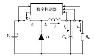
电流滞环Buck DC-DC变换器的组成原理如图 1所示。

Buck变换器工作在连续导电模式((CCM))时,滞环电流控制下的电感电流波形如图 2所示。其中IL(t)是期望的平均电感电流,ΔI是设置的电流滞环宽度,IL(t)+0.5ΔI是电流滞环上限,IL(t)-0.5ΔI是电流滞环下限。

-
与其他电压误差或电压滞环控制的控制器相比较,滞环电流控制器具有以下优点[2]:
1) 稳态特性好,由于是通过实时负载和期望输出电压计算输出电流从而控制电感电流,具有更高的控制精度;
2) 由于采用电流跟踪控制,输入电压的突变不会对输出电压的平均值产生任何影响,只对纹波有影响;
3) 由于直接控制输出电流,适合用于多模块并联组合及智能均流。
-
原有的电流滞环控制方法中,暂态过程控制和稳态过程控制采用相同策略,如式(1)所示。通过设定期望输出电压,采样实时负载,计算电感平均电流,设置滞环宽度,进行实时控制。
为完成负载突变实验结果分析,根据需求设计硬件电路参数为:L=700 mH,C=1 200 mF,滞环宽度ΔI=100 mA,输入电压范围8~25 V,输出电压为额定值5.0 V。负载电流变化范围为0.18~1.13 A。
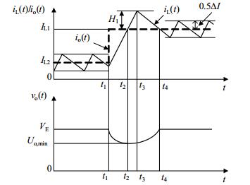
负载电流突增暂态过程测试结果如图 3所示,输出电压的负载调整率为0.55%,动态响应时间大于700 μs。从图 3可以看出,负载电流从0.18 A突增为1.13 A后,电感电流上升到新的电流滞环上限后开关管即刻关断,虽然符合滞环电流控制策略,却导致输出电压减小后无法恢复到突变前的电压值。要解决这一问题,必须适当增加开关S的导通时间,使输出电压可以快速恢复到期望输出值。也就是需要设定在负载电流突增过程中开关S合理的关断时间点。

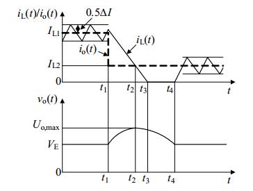
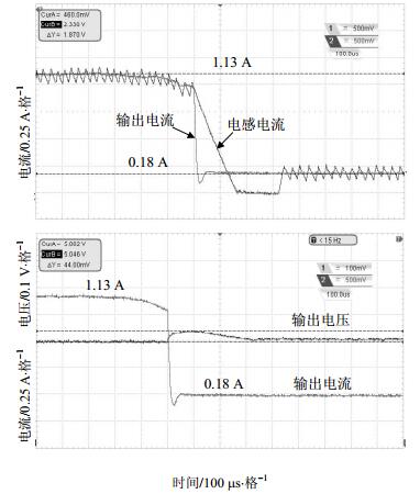
负载电流突降暂态过程测试结果如图 4所示,输出电压的负载调整率为0.76%,动态响应时间大于700 μs。

从图 4可知,负载电流从1.13 A突降为0.18 A后,电感电流下降到新的滞环下限后开关管即刻开通,虽然符合滞环电流控制策略,却导致输出电压增大后无法恢复到突变前的电压值。同样要解决这一问题,必须适当增加开关S的关断时间,使输出电压可以快速恢复到期望输出值。即需要设定在负载电流突降过程中开关S合理的重新开通时间点。
1.1. 电流滞环控制原理及优越性
1.1.1. 电流滞环控制原理

1.1.2. 电流滞环控制的优越性
1.2. 原有电流滞环控制实验结果分析


-
通过实验分析,原有的电流滞环控制方法在BUCK变换器的稳态过程和输入电压变化过程中,都有较好的控制效果,因此,本文只对发生负载突变时的控制策略进行改进,以获得更好的动态响应特性及更小的负载调整率。
-
当负载电阻突然从RL2减小到RL1,即输出电流从Io2突增到Io1,平均电感电流从IL2突增到IL1,过渡过程分为三3个阶段,等效电路如图 5所示。

第一阶段(t1~t2)如图 5(a)所示,此时开关S开通,电感电流增大,电容放电,电流关系为:
根据电感L和电容C的伏安关系,可推导得到这一过程中的输出电压uo(t)为:
其中式中,VE是期望输出值,;Vi是输入电压值,;L是电感值,;C是输出端滤波电容值。
t2时刻,电容的放电电流为零,输出电压值达到“下冲”最低点,可计算得第一阶段持续时间Δt1为式(4)所示:
最低点电压Uo, min为:
第二阶段(t2~t3)如图 5(b)所示,此时,开关S继续开通,电感电流继续增大,而电容开始充电,输出电压回升,电流关系为:
同样推导得到这一过程输出电压uo(t)如下式(7)所示为:
其中式中,iL(0)=IL2+(Vi-VE)t2/L。
假设,开始时刻t2=0,则t3=Δt2,t3时刻电感电流为最大值IL1+H1,得第二阶段的持续时间Δt2为式(8)所示:
第三阶段(t3~t4)如图 5(c)所示,此时,开关S关断,电感电流减小,电容继续充电,电流关系为:
这一阶段的输出电压uo(t)如下式(10)所示为:
假设开始时刻t3=0,则t4=Δt3,t4时刻输出电压恢复到期望值且电感电流为IL1,第三阶段的持续时间Δt3为:
所以,在整个负载突增的暂态过程中,电路的动态响应时间Δt为:
综合上述3阶段可得负载电流突增过程电流、电压应如6图所示。
设K=(Vi-VE)/VE,ΔIL=IL1-IL2,由图 6有:

在过渡过程中,电容的充电电荷等于放电电荷,有:
综合式(13)~式(15),有:
-
当负载电阻突然从RL1增大到RL2,即输出电流从Io1突降到Io2,平均电感电流从IL1突降到IL2过渡过程分为三个阶段, 等效电路如图 7所示。

第一阶段(t1~t2)如图 7(a)所示,开关S关断,电感电流减小,电容充电,电流关系为:
推导得此阶段的输出电压uo(t)为:
t2时刻,电容的充电电流为零,输出电压值达到“上冲”最高点,可计算得第一阶段持续时间Δt1为:
输出电压上冲的最高点电压Uo, max为:
第二阶段(t2~t3)如图 7(b)所示,开关S关断,电感电流减小,电容放电,电流关系为:
推导得此阶段的输出电压表达式为:
其中式中,iL(0)=IL1-(VEΔt1/L)。
t3时刻,电感电流为零,该阶段的持续时间Δt2为:
第三阶段(t3~t4)如图 7(c)所示,开关S关断,负载电流由电容提供。此阶段的输出电压uo(t)如下式(24)所示为:
t4时刻,输出电压恢复到VE,第三阶段的持续时间Δt3为:
所以,在负载突降的暂态过程中,电路的动态响应时间Δt为:
综合上述3阶段可得负载电流突降过程电流、电压变化应如图 8所示。

-
在工作过程中软件判断电路是否发生负载突变,并且判断负载电流突增还是突降,如果是负载电流突增,就延长开关导通时间,使电感电流持续上升到突增后的平均电感电流值加设定的H1值时再关断开关,H1的具体值由式(16)计算获得。控制策略如下式所示:
如果是负载电流突降,就延长开关关断时间,直到输出电压回落到期望输出值之后,并且同时满足电感电流小于滞环下限的条件时再开通开关。控制策略如下式所示:
2.1. 负载电流突增过程分析

2.2. 负载电流突降过程分析

2.3. 负载突变过程控制策略的制定
-
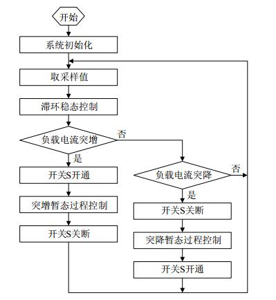
系统程序流程如图 9所示。

设计采用ARM-STM32F407VGT6作为主控制芯片,具有1 MB Flash,192 KB RAM,3个内置高速ADC和DMA等外设资源。系统上电初始化后,取电感电流、输出电流、输出电压、输入电压的采样值,计算出所需要的平均电感电流,执行电流滞环稳态控制。然后判断负载电流是否突变,如果没有,则程序返回继续取采样值执行下一个循环;如果负载突变,程序执行负载电流突变的暂态过程控制策略,分别为负载电流突增过程控制和负载电流突降过程控制。
-
改进后电流滞环控制策略电路参数设置与改进前的相同,即取L=700 mH,C=1 200 mF,滞环宽度ΔI=100 mA,输入电压为额定值DC 18 V,输出电压为额定值DC 5.0 V,输出负载电流范围为0.18A~1.13 A。
-
图 10为开关管驱动波形与电感电流波形,在额定输入电压18 V下测得开关频率为49 kHz。

-
改进后的负载电流突增暂态过程测试如图 11所示,输出电压的负载调整率小于2‰,动态过程响应时间约为170 μs,暂态过程中输出电压“下冲”值不低于4.98 V。

图 11与图 3相比较,可以看出改进后的控制策略使得输出电压在“下冲”后很快恢复到期望值5.0 V,暂态过程的恢复时间和输出电压的负载调整率有了明显改善。
-
改进后的负载电流突降暂态过程测试如图 12所示,输出电压的负载调整率小于3‰,动态过程响应时间约为340 μs,暂态过程中输出电压“上冲”值不高于5.046 V。

图 12与图 4相比较,可以看出改进后的控制策略使得输出电压在“上冲”后很快恢复到期望值5.0 V,暂态过程的恢复时间和输出电压的负载调整率有了明显改善。
4.1. 开关频率测试

4.2. 改进后的负载电流突增响应测试

4.3. 改进后的负载电流突降响应测试
-
通过硬件测试,验证了改进后的控制策略的可行性和优越性:
1) 改进后电流滞环控制策略使电路具有相同的稳态特性的同时,明显改善了负载突变时的动态特性,且克服了改进前负载调整率差的问题;
2) 与参考文献[10]等其他电压反馈控制法相比,改进后的滞环电流控制法不仅可以获得控制精度高和纹波小等稳态特性,同时具有动态响应时间短和输出电压超调量小的特点。

 DownLoad: