 ISSN
ISSN 


-
Quasi-optical mode converters (QOMC) are mainly applied in high power gyrotrons in millimeter and sub-millimeter wave range by transforming the cavity-generated high-order cylindrical waveguide TE modes into linearly polarized fundamental Gaussian- like beams, which can be directly used for low-loss transmission in free space[1-2]. The QOMC inside the gyrotron vacuum envelope directly after the cavity enables separation of the spent electron beam from the RF power. That allows for a depressed collector, which increases tube efficiency and decreases the size and cooling requirements for collector[3-4]. QOMC is a proper combination of a specific mode-converting waveguide slot radiator (launcher) together with a few curved mirrors[5-6]. In order to get a superior quality output beam with low diffraction losses and high purity, a dimpled-wall (Denisov-type) launcher and a mirror system are usually adopted[7-8].
HTML
-
The Denisov-type launcher with deformed wall converts the high-order waveguide mode into Gaussian-like distribution on the waveguide wall before it is radiated from the waveguide cut[9]. Currently, many kinds of methods have been proposed for analysis and synthesis of the launcher, such as analytical methods, formulation of the scalar integral equation (SIE), and the magnetic field integral equation (MFIE)[10-14]. In this paper, an improved method for analyzing the radiation characteristic of the Denisov-type launcher is employed[15-16]. Through decomposing the launcher into an open-end waveguide and a helical cut, radiations from the launcher could be represented in terms of radiation fields by the circular waveguide and the helical cut. The coupled-mode theory is adopted to investigate the dimpled-wall Denisov-type launcher, where the waveguide tapper is also taken into account[17]. The vector diffraction theory[18-19] is used to analyze the radiated fields. The radiated electromagnetic waves at an observation point can be calculated with the Stratton-Chu formula, which is a vector formulation of Huygens' principle, by integrating the response to the point source Green's function over all source regions. Based on abovementioned method, a computer code has been developed for calculating the field of the launcher. For a 0.42 THz-TE17, 4 gyrotron, the profile of the launcher inner wall can be described as
where ${r_0} = 4{\text{ mm}}$, $\alpha = 0.004$, ${\delta _1} = 22{\text{ }}\mu {\text{m}}$ and ${\delta _2} = $ $37{\text{ }}\mu {\text{m}}$, $\Delta {\beta _1} = 0.582{\text{ m}}{{\text{m}}^{ - 1}}$ and $\Delta {\beta _2} = 0.061{\text{ m}}{{\text{m}}^{ - 1}}$, ${l_1} = 1$ and ${l_2} = 3$, and $\varphi $ and $z$ are the angular and axial coordinates, respectively.
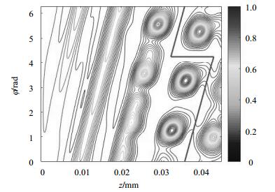
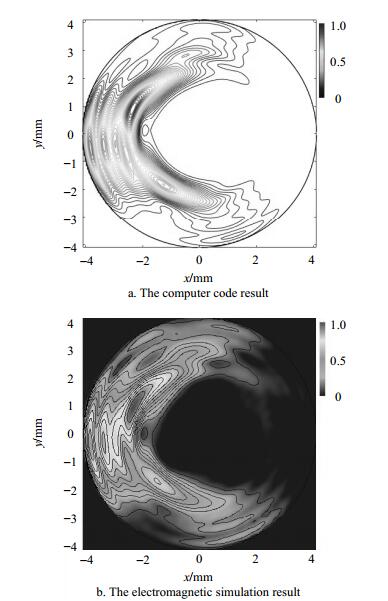
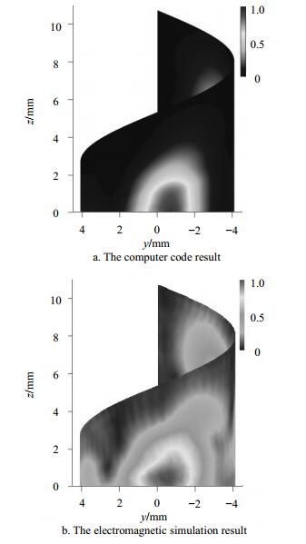
The field distribution of the launcher evaluated by the coupled-mode method is shown in Fig. 1, which is evaluated over the entire launcher wall surface from 0 to 43.02 mm for $z$ and 0 to $2\pi $ for $\varphi $. At $z = 0$, corresponding to the start of the wall variation, a pure rotating TE17, 4 mode is injected. By travelling along the $z$ axis, the power of the main mode is coupled into several mixed modes through the wall perturbations to form a Gaussian-like filed distribution on the waveguide wall. The helical cut of the launcher is located at $\theta = 4.26{\text{ rad}}$, begins at $z = 32.35{\text{ mm}}$, and the cut length is 10.67 mm. Fig. 2a shows the field distribution of the waveguide port before the helical cut, which is compared with the result shown in Fig. 2b simulated by a commercial electromagnetic simulation software FEKO. Regarding the field shown in Fig. 2 as an original source, the field on the helical cut is evaluated by using the improved method and modified Stratton-Chu equations. The result in Fig. 3a is calculated with the code and the result in Fig. 3b is obtained by using the simulation tool. The results indicate that the field intensities are very small along the Denisov-type launcher cut, which can effectively decrease the diffraction losses, and the field can be radiated directionally without side lobes by the launcher.

Figure 1. Normalized field distribution on the unrolled waveguide wall of the launcher (The red line represents the launcher cut)

Figure 2. Normalized field distribution at the waveguide port before the helical cut

Figure 3. Normalized field distribution on the launcher
-
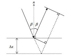
In order to get an output beam with a higher conversion efficiency and higher correlation coefficients to the desired fundamental Gaussian mode, a quasi-elliptical mirror and two adapted phase- correcting mirrors are used to reflect and focus radiated fields from the launcher. The quasi-elliptical mirror is a kind of bifocal mirror which has been studied[20]. And focal lengths of the quasi-elliptical mirror should be carefully designed for matching the asymptotic beam growth (ABG) angle ${\theta _0} = {\lambda _0}/(\pi {\omega _0})$ (${\lambda _0}$ is the wavelength and ${\omega _0}$ represents the beam waist) of the fundamental Gaussian wave beam to provide a high conversion efficiency[8]. For a high-order gyrotron operating mode, the quasi-elliptical reflector could not focus the complicated input well in both angular and axial directions. Therefore, two adapted phase- correcting mirrors are employed to continue focusing the output beam and improving its quality, which are optimized with the error correction Katsenelenbaunm- Semenov Algorithm (KSA)[21]. The main idea of KSA is to reduce the error between the propagating beam and desired field distribution by introducing a mirror deformation, which changes the phase differences, as shown in Fig. 4.

Figure 4. Phase shift on a perturbed surface of a phase correcting mirror
where ${\phi _1}$ is the phase of one field component propagated to one mirror and ${\phi _2}$ is the phase of the desired field back-propagated to the same mirror, and $\beta $ is the angle of incidence.
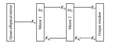
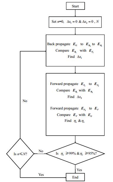
A pictorial explanation of KSA for two phase correctors is presented in Fig. 5. At first, the starting surfaces (initial guess) of the phase correctors are planer-shaped. In Fig. 5, the initial incident field radiated from the quasi-elliptical mirror ${{{\mathit{\boldsymbol{E}}}}_{F1}}$ and the target beam ${{{\mathit{\boldsymbol{E}}}}_G}$ at the output window can be regarded as linearly polarized. ${{{\mathit{\boldsymbol{E}}}}_{F1}}$ is propagated through (reflected) Mirror 1 and acquires an extra phase change, and ${{{\mathit{\boldsymbol{E}}}}_G}$ is back propagated through (reflected) Mirror 2 and also attains an extra phase change. Initially, these mirrors have no perturbations so the extra phase changes are zero. Then ${{{\mathit{\boldsymbol{E}}}}_G}$ is back propagated to Mirror 1, resulting in a field distribution ${{{\mathit{\boldsymbol{E}}}}_{B1}}$. $\Delta {x_1}$ is obtained by applying Eq. (2), taking as the phase difference between ${{{\mathit{\boldsymbol{E}}}}_{F1}}$ and ${{{\mathit{\boldsymbol{E}}}}_{B1}}$, and it is added to the perturbation on Mirror 1. This process is repeated for Mirror 2, and ${{{\mathit{\boldsymbol{E}}}}_{F1}}$ with an extra phase $2{k_0}\Delta {x_1}\beta $ is forward propagated to Mirror 2, resulting in a field distribution ${{{\mathit{\boldsymbol{E}}}}_{F2}}$. $\Delta {x_2}$ is obtained by applying Eq. (2), being taken as the phase difference between ${{{\mathit{\boldsymbol{E}}}}_{F2}}$ and ${{{\mathit{\boldsymbol{E}}}}_{B2}}$, and then it is added to the perturbation on Mirror 2. These steps can be repeated until convergence is achieved, for example, correlation coefficients (${\eta _s}$ and ${\eta _v}$) between ${{{\mathit{\boldsymbol{E}}}}_F}$ and ${{{\mathit{\boldsymbol{E}}}}_G}$ are greater than a chosen value. And the flowchart of this algorithm is presented in Fig. 7. The target field ${{{\mathit{\boldsymbol{E}}}}_G}$ is a fundamental Gaussian mode propagating along the z-direction, and can be described as[22]

Figure 5. Pictorial illustration of KSA for two phase-correctors
where ${w_G}$ is the beam waist of the Gaussian mode.
In the procedure, the beam waist is about $2\;{\text{mm}}$. The correlation coefficients are used to examine the convergence of the iterative optimization, for example, the scalar correlation coefficient satisfies ${\eta _s} \geqslant 99\% $ and vector correlation coefficient satisfies ${\eta _v} \geqslant 95\% $, which means that a very high purity Gaussian beam output is demanded. Theoretically, the perturbation on the reflecting mirror could be obtained by applying Eq. (6), in which the phases of forward and backward propagating waves are wrapped. Because of the wrapped phase varying periodically in the range $[- \pi, + \pi )$, as a matter of fact, it brings out that the phase-correcting mirror with complicated perturbation may not be manufactured exactly. Hence, phase unwrapping technique should be applied to smoothen the mirror surface via converting the phase into the range $(- \infty, + \infty )$, which is referred to as unwrapped. After making the phase distributions smooth based on the phase unwrapping method, smooth phase shifters responding to the deformations of mirrors could be created from their differences. The problem of unwrapping the phase on the planar-based mirror can be treated as two-dimensional (2D) phase unwrapping, which has been solved effectively by using different kinds of methods[23-24]. In this paper, a 2D quality guided path following the phase unwrapping algorithm[25] is employed to solve the phase unwrapping problem.

Figure 7. Flowchart of iterative algorithm for mirror system optimization
-
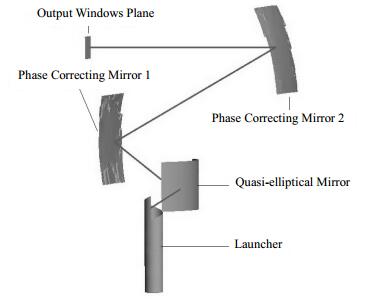
Based on the abovementioned method and algorithm, a mirror system has been designed and field distributions have been also calculated. The iterative algorithm begins to converge after about 30 iterations. The profile of QOMC is shown in Fig. 8. Overall sizes of the phase-correcting mirrors are about $40*40\;{\text{m}}{{\text{m}}^2}$.

Figure 8. The profile of QOMC
Amplitude and phase distributions at the output window calculated by a computer code and simulated by the electromagnetic software FEKO are shown in Figs. 9-10, which indicates that a well-focused wave beam has been obtained. The scalar correlation coefficient ${\eta _s}$ and vector correlation coefficient ${\eta _v}$ used as the criteria for the descriptions of the results' accuracy are estimated as
where ${A_1}$ and ${A_2}$ are two vectors, which can represent the numerical and simulated field components, respectively. In above formulae, if ${A_2}$ is an ideal fundamental Gaussian distribution, then ${\eta _s}$ and ${\eta _v}$ give fundamental Gaussian mode scalar and vector contents of the field distribution ${A_1}$ and estimate its Gaussian mode purity. Finally, the power conversion efficiency of the QOMC ${\eta _\varepsilon }$ is estimated as

Figure 9. Normalized field distribution at the output window.

Figure 10. Phase distribution at the output window.
where ${P_0}$ is total power injected into the launcher, ${{\mathit{\boldsymbol{E}}}}$ and ${{\mathit{\boldsymbol{H}}}}$ represent electric field and magnetic vector fields at the output window, and the superscript "*" denotes the conjugate of a complex function.
There is a good agreement between the two field distributions. Scalar and vector correlation coefficients of the fields calculated by the computer code related to the simulation results are given in Table 1. Table 1 also gives the power conversion efficiency of QOMC. The results show that after being prebunched by the Denisov-type launcher, focused and corrected by the mirror system, a well-focused wave beam is obtained. The power conversion efficiency is 98.5%, and the fundamental Gaussian mode scalar and vector contents are 99.7% and 97.5%. The corresponding simulation results are ${\eta _\varepsilon } = 97.4\% $, ${\eta _s} = 99.1\% $, and ${\eta _v} = 97.3\% $, and the relative deviations between numerical calculation and simulation results about ${\eta _\varepsilon }$, ${\eta _s}$ and ${\eta _v}$ are 1.1%, 0.6% and 0.2%, respectively. The fact that the numerical results yield slight difference from the simulation results can be attributed mainly to two factors. One is the different ways of meshing and solving methods. The other is due to truncation errors of the model size that the complicated and irregular models of Denisov-type launcher and phase correcting mirrors are unable to be directly built, which has to be imported from the professional CAD software.
Conversion efficiency Gaussian mode contents ${\eta _\varepsilon }$ /% ${\eta _s}$ /% ${\eta _v}$ /% Numerical result 98.5 99.7 97.5 Simulation result 97.4 99.1 97.3 Relative deviation 1.1 0.6 0.2 Table 1. Comparisons between numerical and simulation results


-
Theoretical investigation on a highly efficient quasi-optical mode converter for a 0.42 THz-TE17, 4 gyrotron is presented in this paper. The converter consists of a dimpled-wall Denisov-type launcher, a quasi-elliptical mirror, and two phase correcting mirrors. The operation of the launcher has been analyzed by using the coupled-mode theory; fields on the helical cut and mirrors have been calculated with the vector diffraction theory; the phase-correcting mirrors have been optimized based on the Katsenelenbaunm-Semenov algorithm and phase unwrapping technique. A computer code has been developed to evaluate the field distributions, which is compared with that obtained by using the simulation tool FEKO. There are small relative deviation values between the results. It shows that the dimpled-wall Denisov-type launcher generates a Gaussian radiation pattern with low diffraction losses, and the wave beam is corrected by the mirror system. A well-focused wave beam is achieved with a high Gaussian mode purity (scalar content greater than 99.1% and vector content greater than 97.3%) and a high power conversion efficiency greater than 97.4% at the output window.

 DownLoad: